MJLJ V4 in testing
Moderators: JeffC, rdoherty, stieg, brentp
MJLJ V4 in testing
Since the microcontroller used by MJLJ V3/V2 had been discontinued by Freescale, we knew we eventually needed to migrate to a new processor. That time has come! Introducing: MJLJ V4.
We identified a new processor, the HC908QB8 processor from Freescale, which is very similar in capability and offers a bit more RAM to play with. Once we realized porting the existing V3 code would be fairly easy, we set out to adapt it to the existing V3 board. As it turns out, we couldn't leave an old design alone- there were some annoyances and fixes that really needed attention.
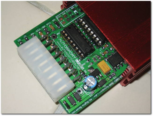
If the pictures make the changes seem dramatic, they're not really. Realize that V4 is functionally identical to V3, save one new feature. Here's the summary list of changes:
* New processor with V3 ported code
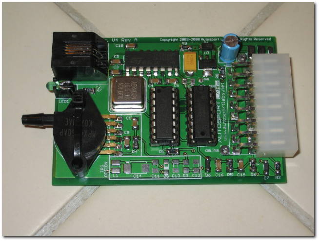
* New board design replaces discretes with 1206 and larger surface mount components, to retain relatively 'DIY friendly' kit build-ability.
* New fancy case
* New temp/ aux input circuit with firmware support
* Pads to integrate case mounted hard rev limiter
* Corrected option Input circuit- simplifies switch wiring
* TACH_OUT improvements- now with 12v 50% duty cycle output
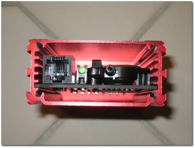
* Addition of power LED
* space-saving RJ11 connector for PC serial connection
* moved MAP sensor to eliminate tube and bulkhead fitting
For V3 users- you're haven't been left behind!! The same temp/analog input feature can be enabled via the 'AUX' pad on your board plus some additional components, and of course, a firmware update.
We're actively testing and with essentially the same circuit we anticipate a fairly short testing cycle. Of course, we will offer frequent updates on our progress. In a few short days I will project a firm timeline for production availability.
Please fire away with any questions. In the meantime, here are some pictures:
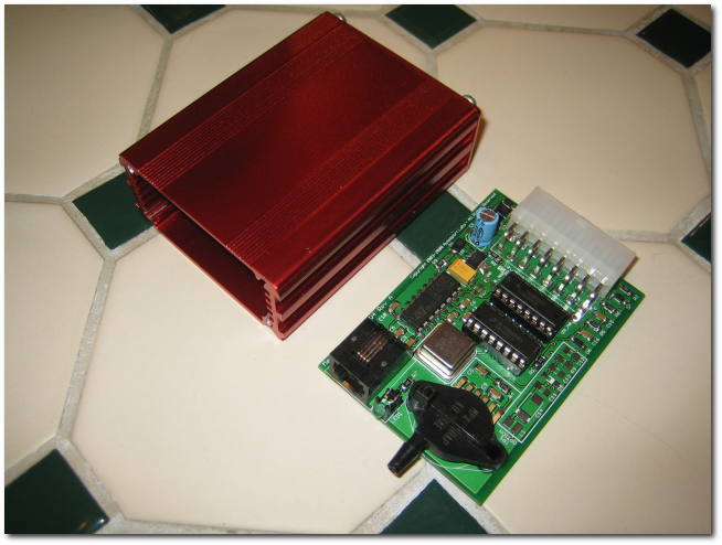
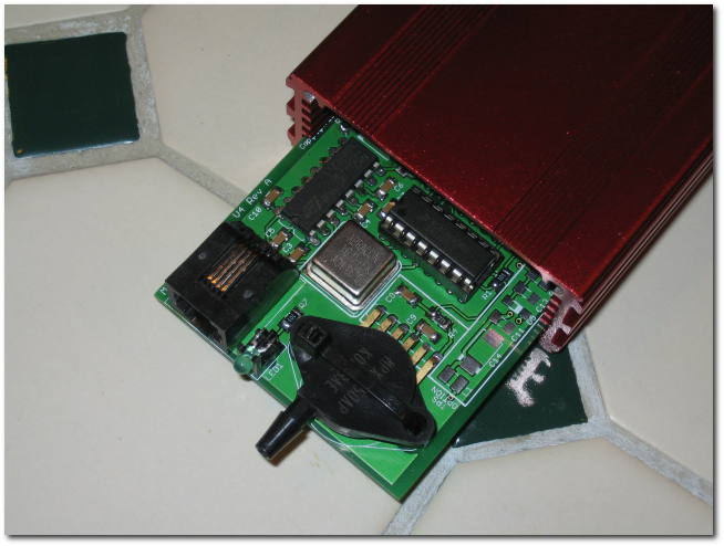
Looks hot, Brent, and I'll admit I feel an urge to order... I can't help but think that the change to the map sensor
mounting, and the removal of the hose and sidewall fitting, is a bad move though. Looks like any struggle to
remove the vac hose is going to mean stress on the map sensor and it's hold-downs.
Nick
mounting, and the removal of the hose and sidewall fitting, is a bad move though. Looks like any struggle to
remove the vac hose is going to mean stress on the map sensor and it's hold-downs.
Nick
Hi Nick,
The MAP sensor body is made of a extremely durable epoxy material- there have a few times where I've placed considerable stress on the hose connector, without any problems. I'm reasonably confident it won't be an issue.
Last edited by brentp on Sun Apr 13, 2008 6:32 pm, edited 1 time in total.
-
- Posts: 204
- Joined: Tue Feb 14, 2006 2:14 pm
- Contact:
Thanks, David.
Megajolt 2 and everything else that will use the CPU module will have a USB interface, which enjoys native support by the 32-bit ARM processor.
So, just as we iron out nearly all of the USB-Serial adapter problems, we'll probably have a whole host of new issues with the USB interface and the various windows drivers! Oh goody, I just can't wait!!
Gav, thanks for the feedback. The reason why I believe the sensor mounting to be robust is twofold:
1- as before, the case of the sensor is made of extremely durable epoxy. It is remarkably strong. So just on it's own, the sensor is pretty good.
2- When mounted in the case, the hole in the end plate + the rubber sidewall of the hose will significantly restrict side-side motion. I realize this is not immediately apparent since I didn't post pics with the unit fully assembled...
In practice I believe this will prove to be a very minor concern, at best.
Thanks again!
I know you're probably tired of hearing this, but does this processor perchance offer knock sensing and response? Any chance for future upgrades to provide this functionality?
I have a client for whom I'm building a supercharged engine and we would very much like to be able to use the megajolt system, however, for obvious reasons, knock control is very important.
Cheers,
PT
I have a client for whom I'm building a supercharged engine and we would very much like to be able to use the megajolt system, however, for obvious reasons, knock control is very important.
Cheers,
PT
Wrenching to riches!
V4 will offer an auxiliary analog input channel which can accept a signal from an outside source and modify the current ignition advance +/- based on the level of that signal. Initially this will be intended for temp sensors- such as for improving warm-up conditions- but in theory other signals, such as an input from a wideband O2 module or other sources can be accepted as well.
For knock sensing, you would need an external module which appropriately detects knock condition and translates it into a signal that can be consumed by the MJLJ AUX input, where the firmware could act upon it. There are other details, but in a nutshell, that is how it could be supported in V4.
In-built knock sensing is far beyond the scope of the MJLJ due to complexity. It's a candidate for a future project.. but to do it *right* would need something with the sophistication on the order of the J&S Safeguard unit-- and lots of engines to sacrifice. There are other options- one example is to use a knock sensor module & matching sensor lifted from a GM vehicle. These options offer varying levels of effectiveness since they were likely designed to work with a particular engine.
Hope this help,
Megajolt 2 and everything else that will use the CPU module will have a USB interface, which enjoys native support by the 32-bit ARM processor.
So, just as we iron out nearly all of the USB-Serial adapter problems, we'll probably have a whole host of new issues with the USB interface and the various windows drivers! Oh goody, I just can't wait!! """
What does that mean? ;P
How do you load your ignition values onto the v4 board? What do you need? Cables wise, if it doesn't use the USB anymore? Sorry my knowledge of pc connectors is pretty bad.
V4 update
Here's an update on what you can expect with the new V4 firmware. V3 users will benefit from most of these updates, via a separate firmware update following V4 availability.
Aux Input capability
The Auxiliary input will allow you to calibrate the raw voltage to a scaled value, very similar to the load axis on the ignition map. This way you can map temp sensors and other sources to some meaningful value.
Aux Input advance correction
There will be a 10 point interpolated 2D map of Aux value Bins vs. advance correction values. During operation, a correction value will be read from this 2D table based on the Aux input value. This correction will modify the base advance +/- 59 degrees, railed at 0 or 59 degrees. V4 will have this 2D correction map along with the regular ignition map, which means it benefits from dual ignition map switching. For V3 users, this map will be stored in the 'global config data', where you will have only one correction map to work with.
Aux Input Peak Decay
I'm looking to implement a feature where the correction is held at the peak value for some configurable delay period (X ignition events). This could be useful for receiving input from an external knock detection unit. Feedback?
Trigger wheel offset
There will be a settable trigger wheel offset +/- a few degrees. Note any adjustment will cause the ignition advance to rail by the adjustment amount at the extents.
Cranking advance
The cranking advance will move to a setting in the global configuration options rather than at map location 0,0.
Configuration software changes
Updates to the configuration software will reflect these capabilities.
We will be completing the V4 build and install documents in the near future.