Page 1 of 1
V3 Board and Hard Cut internal Wiring...?
Posted: Tue Aug 30, 2011 8:30 pm
by teds
Hi there can anyone point me in the right direction with this please.
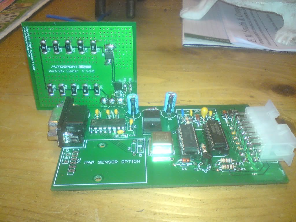
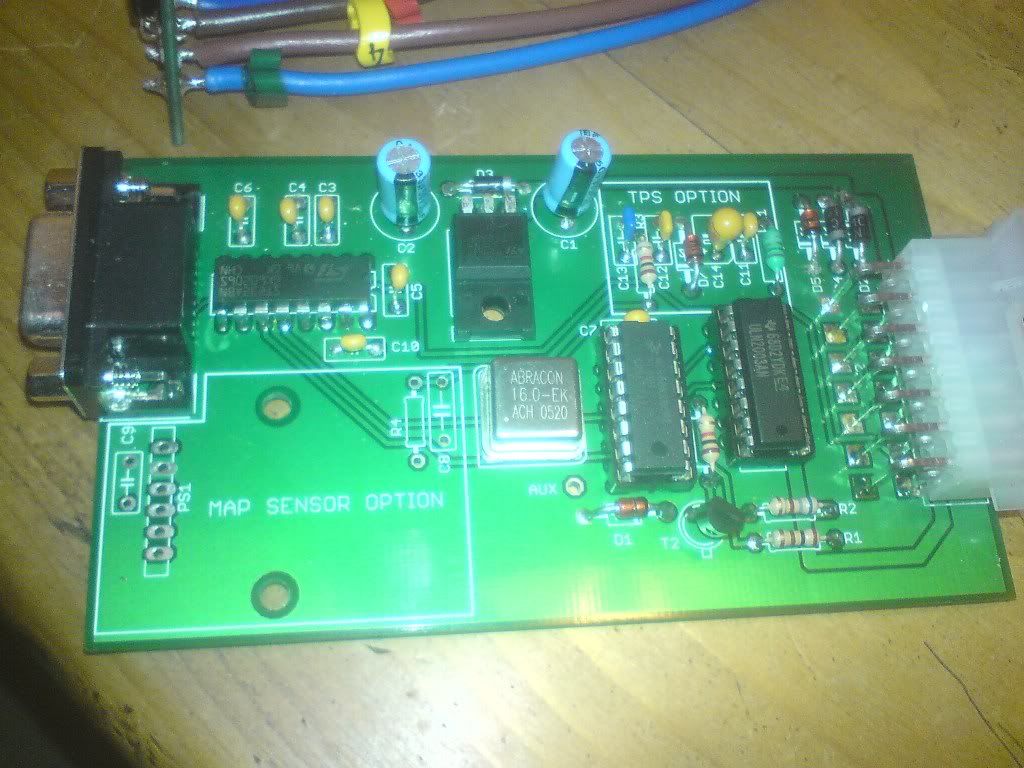
I require help with the internal wiring on my V3 board. I've soldered wires onto the Hard cut board Coil , +12 , Trig, Gnd.

But where do I connect / patch into the V3 board.?

I've looked on the site, but now I'm more confused,
Any help greatly appreciated.
Teds
Posted: Sun Sep 04, 2011 6:27 pm
by brentp
HI,
Since the Hard Rev Limiter board was developed after the V3 controller, the V3 boards never had specific spots to solder in the connections for the Hard Rev Limiter.
To mount it internally, we recommend you solder each lead to the backside of the molex connector. Look at the wiring diagram pinout for the V3 controller:
http://www.autosportlabs.net/MJLJ_V3_ve ... g_the_MJLJ
...and solder the GND, +12V and TRIGGER to the respective pins of the molex connector. Take extra care to make sure you have the correct pins selected on the back side of the connector!
* In the diagram the "REV LIMIT" control is the trigger into the hard rev limiter.
* For the COIL_OUT you will need to pass this wire out of the case separately from the molex connector.
* Ensure the 12V power going into the Megajolt is sufficiently capable of supplying power to the coil pack in addition to the Megajolt unit. 14 gauge wire on a 15A circuit would be sufficient.
Let us know how it works out!


