V3.3.0 firmware / configuration software - for V3 hardware
Moderators: JeffC, rdoherty, stieg, brentp
V3.3.0 firmware / configuration software - for V3 hardware
Christmas comes early at Autosport Labs!
Download the BETA V3.3.0 firmware and configuration software here:
http://www.autosportlabs.net/MJLJ_V3_Do ... d_Versions
(Warning: This only works with V3 hardware- V2 hardware support coming soon...)
Remember, this is for V3 hardware. V4 users already enjoy these features!
Feature List
-- Firmware --
* Settable trigger wheel offset
* Dedicated setting for cranking advance (moved away from 0,0 in ignition map)
* Aux channel input (requires hardware patch)
* Ignition Advance correction table
* User output 1-4 can now handle RPM, Aux and Load triggering
* Various bug fixes
-- Configuration Software --
* Ability to set Ignition Advance Correction (Via Global Controller Settings)
* Configure Aux Input feature (AUX input calibration,
* 3D tuning window enhancements
* Datalogging enhancements
* Datalog viewer
BETA RELEASE
This is a beta release!! Bugs will be found!!
I have only bench-tested this release, using my oscilloscope to verify stable operation. Here in the Pacific NW we are currently buried under a full foot of snow, so it is impossible to actually road test this release.
I / the community would appreciate your testing feedback!
If you can test the new firmware on a bench, please do so before running on an engine.
If you must run it on an engine, first test at idle; do not proceed unless you can verify stable and accurate ignition advance using a timing light.
Then, test under low load, low RPM conditions, watching for any stability issues or general 'weirdnesses'.
There is a known issue with the Configuration software: currently the Advance configuration data is not saved along with the Ignition Config data, as it's stored in the Global Configuration Options. I'm trying to figure out how best to do this...
Aux Input
This requires a hardware modification. On the V3 board there is a pad near the processor labeled "AUX". We STRONGLY suggest you build a signal conditioning circuit to place in front of the AUX input to protect your precious processor! you have been warned!
A low-pass filter with voltage clamping to protect your precious processor would be sufficient. Build this circuit onto a small proto board, sized to slide into one of the available slots in the case. To finish it off, mount a plug on the end plate to bring in your signal.
Emulating the V4 Aux input circuit would be a good start. An example circuit is below:
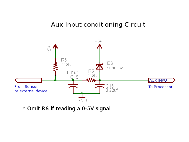
You can use the Aux input for advance correction (see "Global Controller Options" dialog in config software), and you can now program user outputs 1-4 to trigger on an Aux input value.
What would also be useful is a write-up for mapping the output of wideband controller to the aux input. dr.occa had a great start in his post; we should get this into the wiki!
So there you go. I hope this earns me some karma points. Please report your feedback and bug reports on this thread.
Last edited by brentp on Mon Apr 23, 2018 10:27 pm, edited 1 time in total.
I have few questions.
At the local shop they have the following Schottky diodes:
1. BAT 43 DIODA, 30V, 200mA, <5nS, SCHOTTKY
2. BAT 46 DIODA, 100V, 150mA, SCHOTTKY
3. BAT 48 DIODA, 40V, 200mA, SCHOTTKY
4. BAT 49 DIODA, 80V, 1A, SCHOTTKY
5. BAT 85 DIODA, 30V, 200mA, SCHOTTKY
6. BAT 86 DIODA, 50V, 200mA, SCHOTTKY
7. MBR 3045 Dual, Schottky, 45V, 30A, (Tc=105º)
8. PBYR 1645 DIODA, 45V, 16A, SCHOTTKY
9. PBYR 3045 DIODA, 45V, 30A, DUAL SCHOTTKY
10. SB 550 Schottky-GI, 50V, 5A
11. 1N 5819 Schottky-GI, 40V, Uf < 0.6(1A)
which one should I get? Number 1?
And resistors should be 0.25W? 0.5W?
'87 BMW 316 E30
1600cc M10B16
petrol + LPG, MJLJ
1600cc M10B16
petrol + LPG, MJLJ
For 1N 5819 (http://www.semikron.com/internet/gecont/pdf/1099.pdf):
Repetitive peak reverse voltage Vrpm=40V, Surge peak reverse voltage Vrsm=40V, Max averaged forward current Ifav=1A, Max forward voltage Vf=0.9V
Does this sound OK?
Repetitive peak reverse voltage Vrpm=40V, Surge peak reverse voltage Vrsm=40V, Max averaged forward current Ifav=1A, Max forward voltage Vf=0.9V
Does this sound OK?
'87 BMW 316 E30
1600cc M10B16
petrol + LPG, MJLJ
1600cc M10B16
petrol + LPG, MJLJ
Another question.
I downloaded and installed MJLJ Configurator V3.3.0 (and upgraded controller firmware). I added Aux Input Gauge, changed it's name to Coolant Temp, changed units to Celsius, but I am unable to change the numbers on the dial. I'd like it to be ~ -13 to + 115 or something. It seems that Scaling factor at Tools > Auxiliary Input Options can be only 1-4 integer and I need 0.5 or something. The best I found is to set it at 4 and then it reads 0 - 1020.
I did not make necessary electronic to connect coolant temp sensor yet, so I am just asking this in advance.
'87 BMW 316 E30
1600cc M10B16
petrol + LPG, MJLJ
1600cc M10B16
petrol + LPG, MJLJ
Hi Yvan,
The Aux input gauge does not support fractional scaling; only 1x - 4x scale of the *scaled* measured value of 0 - 255. Also, negative numbers are not supported.
For engine coolant temp you can use a 1x scaling and then you would have a realistic scale of 0 to about 120C. (actually, 0 to 255C)
Initially, the measured value from temperature sensor will not correspond to actual temperature; you will need to map the raw ADC value to the desired scaled value. By default, the scale is linear; i.e. 0=0 ... 255=255.
Using a spreadsheet, such as Excel, could be useful to generate all of the data points if the temperature sensor you are using has a reasonably linear response. You will need to take samples at different known temperatures to determine this.
I hope this helps!
So for whatever you connect to aux input the gauge reads 0-255 (or 0-255x2 x3 x4)? 0-5V is also 0-255? You can not change this?
Actually in my case it is not important as I just need to switch aux radiator fan on low at ~91 Celsius (I think), and on high at 99 Celsius. But it would be nice if the gauge would show degrees Celsius.
'87 BMW 316 E30
1600cc M10B16
petrol + LPG, MJLJ
1600cc M10B16
petrol + LPG, MJLJ
I connected my spare temp sensor to MJLJ aux input. I first made slight modification, and soldered parts for AUX signal conditioning circuit directly to MJLJ board (as I not use TPS option). Here is the photo:
- Attachments
-
- AUX signal conditioning circuit
- mjlj-mod-1.jpg (114.13 KiB) Viewed 64238 times
'87 BMW 316 E30
1600cc M10B16
petrol + LPG, MJLJ
1600cc M10B16
petrol + LPG, MJLJ
I then dipped temp sensor in a cup of cold water with ice (0 Celsius or 32 Fahrenheit) and gauge showed 60. At body temperature (36 Celsius or 97 Fahrenheit) gauge reads 20, and at boiling point (100 Celsius or 212 Fahrenheit) gauge reads 2.
Do I have some reverse resistance temp sensor, or what is happening? And since temp sensor is basically variable resistor (1.9 Kohm at freezing point, 450 ohm at body temperature, and 42 ohm at boiling point), I guess that R5 here: http://www.autosportlabs.net/images/1/1 ... ircuit.png is the reason for such a low reading. Can I remove R5 and put a short in it's place (without losing processor protection)?
Second problem. I configured user configurable outputs like at photo below, and it looks to me that when Coolant Temp is at 11 (as it is at the photo), Output 1 should be disabled, 2 enabled, 3 enabled, and 4 disabled. Looking at output LEDs at the right bottom of the photo it is not the case. And that is the feature I need.
- Attachments
-
- mjljV3beta.jpg (93.15 KiB) Viewed 64234 times
'87 BMW 316 E30
1600cc M10B16
petrol + LPG, MJLJ
1600cc M10B16
petrol + LPG, MJLJ
Hi Yvan,
It appears you have a 'negative temperature coefficient' sensor.
You can use the Aux Input calibration table to reverse the readings. Go to "Aux Input Channel Options" and modify the values under "Edit Calibration Values" , to give the readings you desire.
Note the table-
ADC value: the raw value the processor reads from the sensor
Voltage: The voltage this represents on the ADC port
Scaled Value: The translated value *you* specify, between 0-255.
Once the sensor is "calibrated" the measured readings should reflect actual Degrees C.
Since the table is 256 elements long, you can optionally edit the data outside of the MJLJ Config software: save the data to a text file ("Save Calibration"), edit the file, and then Re-Load the calibration data from your modified file.
Regards,
OK, I finished calibration for mu temp sensor (BMW OE: 12 62 1 710 511). If someone else needs it I attached configuration file.
So, now my aux input gauge displays degrees Celsius, but I still have the problem with user configurable outputs. None is switching on and off at preset activation point. It is eather ON if I select "invert" as output mode or OFF for "normal" output mode regardles of how temperature changes.
I have set activation point at, for instance 25 deg Celsius (Scaled Value), but also to the corresponding ADC value.
And I thought that perhaps it is just Configurator that does not lit up bottom right LED-s, so I measured outputs with my ohm meter, and, again, it is ON or OFF.
Is it a bug in the software, or am I doing something wrong?
- Attachments
-
- Celsius5.txt
- (866 Bytes) Downloaded 1588 times
'87 BMW 316 E30
1600cc M10B16
petrol + LPG, MJLJ
1600cc M10B16
petrol + LPG, MJLJ
I made calibration file with Easy Therm: http://www.msefi.com/viewtopic.php?t=10308
After you install run it, choose Celsius or Fahrenheit, measure sensors resistance at three temperatures (easiest is at freezing point, body (or room) temperature, and boiling point), and press calculate. At c:\Program Files\ Easy Therm you will find file "thermfactor.inc" with needed calibration data (in Fahrenheit). You can import that in excel and convert to Celsius (if you want) and change all negative values to zero. Save data from excel column to file.txt and "Load Calibration" at mjlj configurator. Tune it up some more if necessary - that's it, I did it that way.
If someone needs more detailed instructions - just ask
'87 BMW 316 E30
1600cc M10B16
petrol + LPG, MJLJ
1600cc M10B16
petrol + LPG, MJLJ