rotary megajolt

General Megajolt Questions and Answers

Moderators: JeffC, rdoherty, stieg, brentp

dr.occa
Posts: 243
Joined: Fri Feb 23, 2007 10:52 pm
Location: TX

Post by dr.occa »

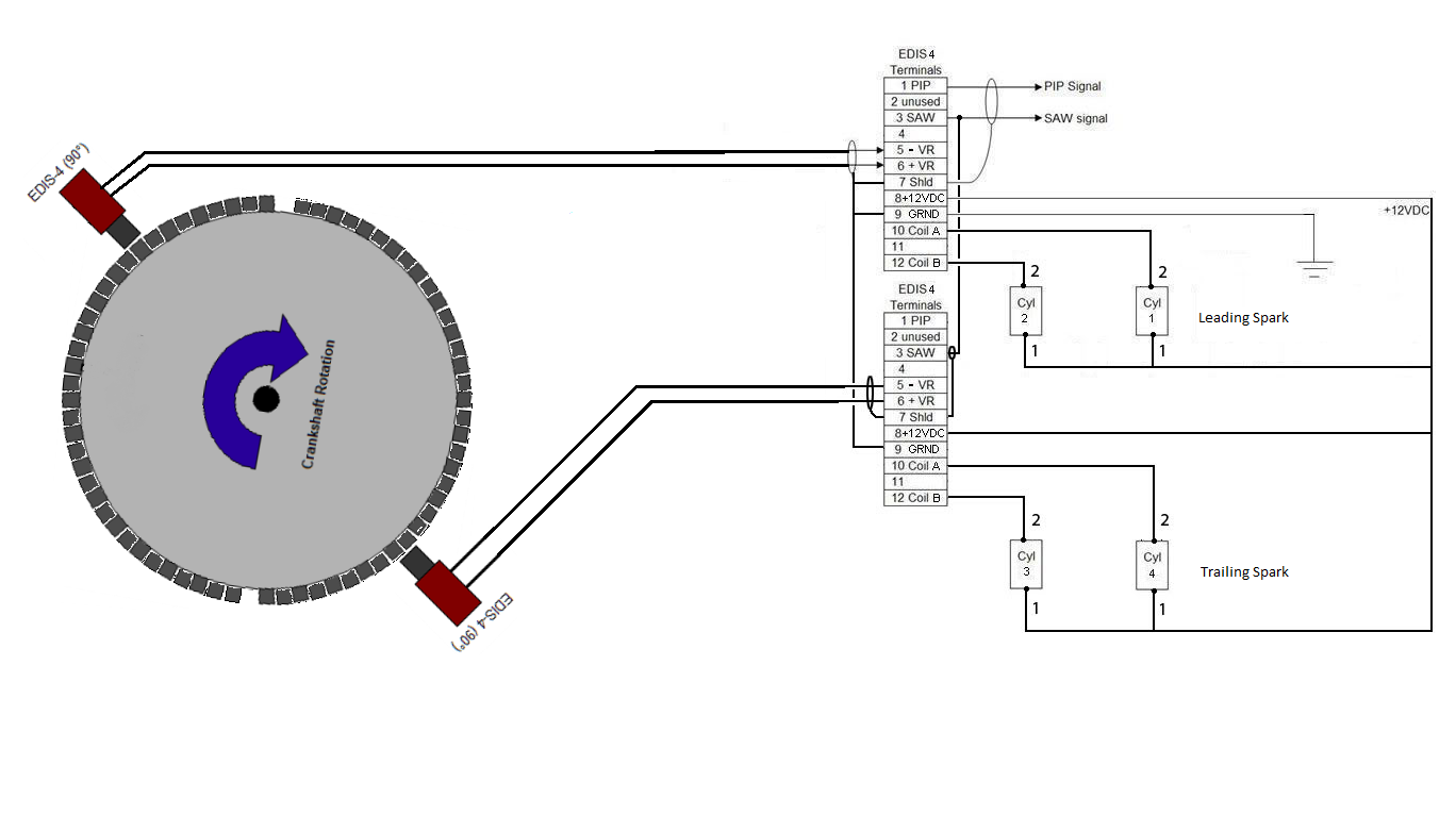
Couldn't this essentially work using a 72-2 crank trigger wheel & x2 VR sensors, x2 EDIS-4 Modules and x4 coil per plugs (taken from the RX-8)?

The VR sensor for the trailing spark is staggered by ~5° in the illustration.

This with still just a single MJLJ unit.

Image
AUTOSPORTLABS
NonStop Tuning
www.86garage.com

"Poverty is not a virtue."

BRUCEROE
Posts: 96
Joined: Wed Mar 03, 2010 10:00 pm

Post by BRUCEROE »

If I read right, a spark plug requires one spark for every crank revolution (360 degrees). If so you can just use a 36-1 tooth wheel on the crank, which fires each plug once a revolution. But it won't be waste fire anymore. The other end of the coil output will need to be grounded to complete the plug circuit. The second rotor I'd expect to fire one half crank turn away from the first, so a 4 cylinder EDIS system ought to do it. A second delayed spark would require a second ignition system. The second VR could be offset the proper number of degrees, or just be programmed with a shifted spark map. That could be done with the same spark map but a different auxillary input to shift everything. It might even be interesting to shift the auxillary input and see if there is a better optimum. With the 2 VRs out of phase, reversing the coil drivers on the second EDIS should bring it back. Possibly the same VR could drive 2 different EDIS, haven't tried that. But I'm not convinced you can share the PIP & SAW signals. good luck, Bruce Roe

Spockie-Tech
Posts: 152
Joined: Wed Jan 02, 2008 12:52 pm
Location: Melbourne, Australia

Post by Spockie-Tech »

Why would you want a 72-2 Tooth Wheel ?

Each EDIS still wants to see a 36-1.. its just the offset sensors that will result in each one firing at a slightly different rate.

I'm not sure about being able to use a single Megajolt though.
From what I read here http://www.megamanual.com/ms2/EDIS.htm
Note that the SAW pulse must be synchronized with the PIP negative going pulse (i.e, when the PIP drops to zero). It cannot be applied asynchronously to the PIP signal, otherwise incorrect advance commands will be interpreted by the EDIS module. SAW should be initiated a short period after the falling edge of the PIP signal.
The SAW (Spark Angle Word) sent from the Megajolt to the EDIS has to be in a precise timing relationship relative the PIP (Position Indicator Pulse /or/ Profile Ignition Pickup) signal.
If you have two EDIS's that are triggering (generating PIP signals) from offset VR sensors, then their PIP signals will occur at different times.. meaning the SAW signal coming from the Megajolt will occur at the wrong time for the delayed EDIS/VR set.

If the offset is less than 8 degrees (before the next PIP pulse) you *might* get away with it, but I wouldnt promise it..

So unless someone more experienced with Rotarys can offer an opinion, it sounds from that like you might need two Megajolts to control two EDISs that are running offset from each other.

Maybe Brent would know more about the timing relationship required between the EDIS and Megajolt.

edit: Heh, Bruce just said pretty much the same thing while I Was typing this.. :)

dr.occa
Posts: 243
Joined: Fri Feb 23, 2007 10:52 pm
Location: TX

Post by dr.occa »

Good stuff, good stuff.

The reason I thought it may work is that I run a single MJLJ with 4 COPs this way in waste spark on my 1.6 4cyl but with a single VR sensor and the EDIS modules in parallel: VR± combined, +12v, Ground and Shield combined, etc...

With the EDIS modules running individual VR sensors nearly at the exact same 90° BTDC (with the Trailing VR sensor ~85° BTDC 180° opposed) the Lead & Trail Coils would fire nearly simultaneously except for the Trailing Coil(s) which should be ~4-5° right behind the leading spark.

The MJLJ would only provide the timing map.

I'm not ruling out necessitating a second MJLJ unit for this to work with emphasis on "if necessary".
AUTOSPORTLABS
NonStop Tuning
www.86garage.com

"Poverty is not a virtue."

orangepeel
Posts: 5
Joined: Tue Aug 03, 2010 4:48 pm

Post by orangepeel »

hey guys, sorry for the absence of posts, i thought it was a dead end and started thinking about other systems. but reading you posts make me think again.
i will have to do more research, :D
cheers
niall

dr.occa
Posts: 243
Joined: Fri Feb 23, 2007 10:52 pm
Location: TX

Post by dr.occa »

It does appear that 2 MJ units would be necessary for this to work properly siting what Spokie previously sited himself regarding synchronous PIP signals, etc...

Even though it would be the extra cost of a second MJLJ unit it would achieve the desired output.
AUTOSPORTLABS
NonStop Tuning
www.86garage.com

"Poverty is not a virtue."

Spockie-Tech
Posts: 152
Joined: Wed Jan 02, 2008 12:52 pm
Location: Melbourne, Australia

Post by Spockie-Tech »

Syncing up the curves in two seperate Megajolt Units while programming them would be a PITA though.. You would have to have a switch to change the serial port from one to the other and make a change, hit program, switch the switch and repeat.

You could *try* a single Megajolt controlling two EDIS units with seperate offset VR sensors.

I havent found any docs that precisely define the amount of time that can elapse from the PIP signal from the EDIS that is allowed to elapse and have the SAW response (from the Megajolt) still considered to be valid.

So if the seperation between the two sensors isnt too great (how far apart are the leading/lagging plugs on a rotary ?), you *might* get away with the PIP signal *to* the Megajolt connected to the leading Coils EDIS unit ouput, and the SAW signal *from* the Megajolt connected to *both* EDIS modules.

From what I have read the PIP/SAW timing relationship isnt too timing critical.. The EDIS can apparently miss a few SAW signals before it drops back into limp-home and revert to 10 degrees timing. So it might work if its just measuring the length of the SAW pulse and not its relationship position wise to PIP.

You could bench test it with a trigger wheel in a drill, two offset sensors in a bracket at the correct angle with two EDIS modules, the single Megajolt and a timing light.

If the spark timing on the leading EDIS varied smoothly with a change in the drill RPM, but the trailing one didnt move (limp home), or jumped around (too far out of time SAW signal), then its a no-go.

If they both advanced and retarded according to the 'jolts curve in sync with each other, then it should be safe to try on an engine.

orangepeel
Posts: 5
Joined: Tue Aug 03, 2010 4:48 pm

Post by orangepeel »

hi guys, thanks for the continuing discussion, way above my head :D
there is about 5-10 degrees between the leading and trailing plugs if that helps??
cheers
niall

dr.occa
Posts: 243
Joined: Fri Feb 23, 2007 10:52 pm
Location: TX

Post by dr.occa »

I still haven't tried testing this on a drill press but going over the setup this should work.

Here's my understanding of the transaction and why I believe it should work:
  • 1. Lead VR sensor sees the missing tooth go by (i.e. 90°) before TDC
    2. He goes and hands the information to MJLJ
    3. MJLJ takes the RPM information -> Hands Lead VR sensor the time to fire
    4. Lead VR sensor goes on his merry way to turn on his coils at the specified time MJLJ told him to
    5. Trailing VR sensor sees the missing tooth go by 5° to 10° after Lead VR sensor sees it
    6. He shows up behind Lead VR sensor and asks for a copy of the same information Lead received from MJLJ
    7. MJLJ gives Trailing VR sensor the same information he gave Lead
    8. Trailing VR sensor goes on his merry way to turn on his coils at the specified time
    - Trailing will always see the missing tooth 5° to 10° after Lead does but he doesn't know that or cares and turns on his coils at the prescribed time based on when HE SEES the missing tooth go by.
Is this a fair analogy of what's going on? And please someone correct me if I've made any mistakes in tearing down the process this way.
AUTOSPORTLABS
NonStop Tuning
www.86garage.com

"Poverty is not a virtue."

dr.occa
Posts: 243
Joined: Fri Feb 23, 2007 10:52 pm
Location: TX

Post by dr.occa »

With a larger dia. 36-1 trigger wheel, it may be possible to place the lead VR sensor at the prescribed 90° (9 teeth) and the trailing VR sensor at 85-80°(8.5 to 8 teeth).
AUTOSPORTLABS
NonStop Tuning
www.86garage.com

"Poverty is not a virtue."

Spockie-Tech
Posts: 152
Joined: Wed Jan 02, 2008 12:52 pm
Location: Melbourne, Australia

Post by Spockie-Tech »

Hmm, I was hopeful until I read this page..
http://www.bgsoflex.com/mjl/mjl_edis_summary.html

this is the worrying bit.. "Note that the SAW pulse must be synchronized with the PIP negative-transitioning pulse - it cannot be applied asynchronously to the PIP signal, otherwise incorrect advance commands will be interpreted by the EDIS". This is the first page I have read that says the timing relationship between PIP and SAW has to be tight.

It still *might* be possible in a different way.

According to that page, The Megajolt must respond to the PIP signal from the EDIS fairly quickly with a SAW (Advance) pulse.

Depending on how the MJ determines the RPM from the PIP signal timing, it might be able to cope with *two* PIP signals (one from each EDIS) and respond to each PIP signal with an individual correctly timed SAW response..

(RPM is a slippery concept in a rotary anyway, with their offset gear driven crankshaft ;) )

But, it all depends on whether the MJ is figuring out the RPM by timing the *length* of the high side of the PIP pulse, or whether it is timing it by measuring the interval *between* PIP pulses.

If its the former, it might still work, if its the latter, then it wont.

If the MJ measures the length of the high side of the pip pulse to determine rpm, and then responds with a timed saw pulse (based on the map), and thats all, then it shouldnt care if another PIP pulse comes along a few degrees later wanting another SAW response.. provided the second PIP pulse (from the trailing EDIS) doesnt arrive while the SAW pulse is still being sent for the previous PIP pulse..

referring to that page, it looks like the maximum length of the SAW pulse is ~1500 microseconds or 1.5 milliseconds.

Now this is where my fuzzy rotary knowledge could trip me up, so I'll do some calculations based on a piston engine and you can see if you can adapt them to rotary-ignitions.

Lets say a 6 cylinder engine doing 7000 RPM (close to the EDIS's maximum - hmm, more on that in a moment).

7000rpm = 116.6 Revs per second. about 8ms (.008 seconds) for each revolution (pretty damn quick !)

Half the cylinders fire each Revolution, so thats 3 cylinders firing within that 8ms, or about 2.8ms between firing events. oh oh, that doesnt sound good.

if we have to fit a SAW response pulse that could be up to 1.5ms in length in between PIPs that could be a mere 2.8ms apart, I think we're in trouble as far as getting two responses in there at high RPM..

This could explain the EDIS's 7000-8000rpm Limit, since somewhere around there the PIP signals are going to start coming faster than the time needed for the SAW response to be sent, although it is an inverse relationship timing signal (the more advance required, the shorter the SAW reponse pulse length.. at 40 degrees advance, SAW is only 500ms (or 0.5ms) long, so that would help keep the from crashing into each other).

But, at say 7000pm, that 2.8ms spacing = 120 degrees of crank revolutions (6cyl = 3 sparks per rev).

if you have two EDIS's connected to one MJ, and the second EDIS sends a PIP signal just 10 degrees later than the first one (instead of 120 degrees later) , then the 2nd PIP signal is going to appear .0002s (200us) after the first. crash.. the second PIP probably just ran over the time that the SAW response to the first PIP is taking, and things are likely to get messy with unpredictable timing on the second EDIS. Even if the second PIP signal didnt confuse the MJ at that point. Bugger.

Additionally, before you go and crunch the numbers for a rotarys timing, it just occurred to me that, that is an EDIS even going to handle the maximum RPM of a Rotary ?

I measured two EDIS-6's a while ago and found they stop sparking somewhere around 7000-8000rpm.. (I forget the exact values, its in a previous post of mine if you want to find it).

I just checked and found that the rotors turn at 1/3 of the output shaft speed, but of course, there are 3 sides to the rotor, so it sounds like you still need 3 sparks per output shaft rev, so 10,000rpm = 10,000 6 cyl rpm as far as the ignition is concerned, even if the rotors are only doing 3300rpm at 10,000rpm shaft speed.

So, what do you typically spin your rotaries up to ? If you're going much past 7000rpm, youre going to pushing the limits of the EDIS module anyway, so whether the MJ can handle it might be a moot point.

Phew, that all sounds rather messy, I hope I'm not making you more confused with all this. :)

dr.occa
Posts: 243
Joined: Fri Feb 23, 2007 10:52 pm
Location: TX

Post by dr.occa »

Sorry to bring this back up nearly 2 years later.

I've got my 12A project up and running and wanted to re-visit this.

Proper timing for my Wankel as per the FSM is ATDC Lead 1 should be 0° while Trail 1 should be 20° ATDC. There should be no advance at 500rpm but at least 10° of advance at 1500rpm on both leading and trailing (so 10° & 30° at 1500rpm for leading and trailing respectively)

My current ignition setup uses the factory distributor as follows:

- Leading VR sensor triggers an MSD 6AL which fires 2 MSD Blaster Coils simultaneously for the leads in waste spark
- Trailing VR sensor triggers a single MSD Blaster Coil which uses the factory cap for the trailing plugs which is essentially factory (I'm using a 4 prong GM HEI ignitor that cost me all but $14 new)

I can do the same for the trailing plugs as I did for the leading plugs by getting an additional coil (giving me a total of 4 - 2 for leading and 2 for trailing), getting an additional MSD 6AL and then just using the distributor trailing VR sensor as a trigger.

The ignition for a 2 rotor motor is treated like a 4 cylinder as per MSD AND Megasquirt.

Given that, I believe it should work with the following:

- 2x EDIS Modules
- 2x MJLJ units
- 2x 36-1 trigger wheels (with the trailing trigger wheel an additional 20° offset from the leading trigger wheel)
- 2x VR sensors
AUTOSPORTLABS
NonStop Tuning
www.86garage.com

"Poverty is not a virtue."

dr.occa
Posts: 243
Joined: Fri Feb 23, 2007 10:52 pm
Location: TX

Post by dr.occa »

I believe this should work.

It would require the following:

2x EDIS-4 modules
2x VR Sensors
2x Megajolt Lite Jr
1x 4 post coil pack

Pin 12 of both EDIS modules just wouldn't be used because the coil for 2 & 3 on a 4 cylinder can't be programmed to spark 20° behind the leading coil even with a separate VR sensor. I don't know of a way to designate a separate one for coil B.

What ever ignition map is used for the Leading coil should be used for the Trailing coil. The location of the Trailing VR sensor 20° after the Leading sensor will just naturally dictate the 20­° stagger.

The only concern now is maintaining good spark above 7500rpm given the limitations of the EDIS units. When taken care of, Rotaries easily see 9K to 10K.
Attachments
Rotary-MJLJ-vrsensor-locations.png
Rotary-MJLJ-vrsensor-locations.png (39.35 KiB) Viewed 29492 times
AUTOSPORTLABS
NonStop Tuning
www.86garage.com

"Poverty is not a virtue."

Post Reply