Finally after 2 years I had enough spare time to convert my project car to Megajolt. I'm using the v3 MAP version.
The car ran on the base map but on idle and in low revs it gives me back fires. so I want to create my own map from the factory specs but I got stuck with the numbers. I used the xsl from this site to help me convert some numbers but still no real luck.
I made a screenshot from the factory specs it is in dutch but pretty self explaining.
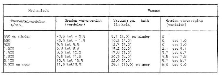
1st colomn is RPM
2nd colomn is advance in degrees
3rd colomn is vac in cm and inches between ()
4th colomn is advance in degrees
The first thing that gives me problems is the RPM. If this is crankshaft rpm I need to multiply by 4. That means up to 9200 rpm but the specs tell me max 6000, so that can't be correct but 550 rpm isn't nearly enough to let it idle.
the second is the inHG /cmHG when I use the calculator in the xsl sheet the lowest load value (ABS:MJLJ) I get is 68 while on most maps it starts at 0.
third I only got 8 value's from the factory spec list and I need 10. Where do you add numbers. I searched for the biggest gaps between value's and added a value in between. But does that mean if you add a value in the RPM between value 7 and 8 you also need to do this for Load between 7 and 8 or can that be between 4 and 5 for example?
Hope somebody can point me in the correct direction.
help with creating map from factory specs
Moderators: JeffC, rdoherty, stieg, brentp
The RPM figures given in your table are for the centrifugal advance, I think. I presume they reach a max and above that won't give you any more. If you just had these and no vacuum correction, you'd end up with a 3D graph that looks like a set of steps. The vacuum will give it curves.
On the .xls you got from this site, have you added in your static advance? For example, for my engine it's 17 degrees - makes a huge difference.
My engine load never drops below about 40 so wouldn't worry about it being above 0. As you rightly said, to get the full 10x10 table you need to add figures where necessary. If your load values only range between 60 and 100 then you can have really fine detail on the map. You don't have to add the numbers between the same range of figures (7 and 8 in your example). Once you get the engine going and log some data you can see where your normal operating range of RPM/load is and adjust the map accordingly
Sorry if I've confused you!
spandit,
thanx for the explanation. I did indeed used a static advance, the documentation said use 6 degrees but to run on ron 95 petrol it needs to be between 8 and 10. So I used 10 as that is what I used with de dizzy setup.
So If I read the RPM table right then the dizzy is designed to create max 13,3 degrees advance from 2300 RPM up to 6000 RPM and never more.
I will try and calculate the value's again and load them into mjlj. thanx again.
wel I tried several options but for some reason it only got worse. I haven't driven it yet just stationary revving. When coming of the thotle it pops and bangs like a full spec rallye car I assume she is running a bit rich.
But when pressing the throttle fast it gives mayor backfires into the air intake, not funny.
My first thought is overfueling but with the dizzy setup I never got backfires just some popping coming of the power. The emmision check lasttime was rich but between limits to pass.
Are backfires generated due to too much correction?
I haven't got a wideband lambda or even a lambda hole in the exhaust (great old cars) but if I make a hole for one does it need to be wide band or will a normal do for average reading.
You could try loading a "flat map" (i.e. all of the same value) into your MJLJ on the switched channel and flicking over to that to see if you can find a value that works. That said, if you unplug the MJLJ and run on EDIS alone, do you have any luck? This should give you a static 10 degree advance, I think. Have you checked with a timing light if things are set up OK?
-
- Posts: 7
- Joined: Fri Apr 29, 2011 5:01 am
@DD
I thought I would chime in on your question about a lambda sensor, only because I have just finished making one for my project. One of the things I learnt about these sensors is that a 'normal' narrow band sensor is pretty useless if your mixtures are way off. They really only tell you if your mixtures are correct, rich or lean, and cant tell you by how much if you are rich or lean. A standard O2 sensor is really only designed to work with a vehicles ecu.
Because of this, I spent the money to build a wideband O2 display which can display readings right across the range from 7 up to 22, and I hope this will let me visualize what's going on during the tuning process.
I'm not sure where you are, but in Australia I got the wideband O2 sensor kit (display and controller) from Jaycar for about $100, and a 5 wire Bosch wideband sensor for another $90. Even if that only saves me an hour on the dyno, I'm still in front. As for fitting the sensor in the exhaust, drill a 23mm hole just after the last merge, tac weld a 22 x 1.5 nut on the hole, screw the sensor in. Job done.
Re what you described for you symptoms, it rather sounds like cam timing. Have you had them out/modified them?
Good luck.
Re: help with creating map from factory specs
Why x4 ?DD wrote:1st colomn is RPM
2nd colomn is advance in degrees
3rd colomn is vac in cm and inches between ()
4th colomn is advance in degrees
The first thing that gives me problems is the RPM. If this is crankshaft rpm I need to multiply by 4.
The table header says ´toerental verdeler´ = rpm distributor and ´vervroeging verdeler´ = advance distributor.
Usually the distributor is driven by the camshaft and runs half the RPM of the crankshaft so you would have to multiply both RPM and degrees advance x2.
So, with an additional static advance of 6 deg (crankshaft), your map should look like this;
Code: Select all
ABS kPa Crankshaft RPM
0 1100 1240 1800 2400 3000 3600 4200 4600 10000
0 6 6 7 15 21.6 24 26.4 29 30.6 30.6
7 6 6 7 15 21.6 24 26.4 29 30.6 30.6
14 7 7 8 16 22.6 25 27.4 30 31.6 31.6
17 9 9 10 18 24.6 27 29.4 32 33.6 33.6
20 13.2 13.2 14.2 22.2 28.8 31.2 33.6 36.2 37.8 37.8
24 16.4 16.4 17.4 25.4 32 34.4 36.8 39.4 41 41
27 18.6 18.6 19.6 27.6 34.2 36.6 39 41.6 43.2 43.2
30 20.4 20.4 21.4 29.4 36 38.4 40.8 43.4 45 45
34 21 21 22 30 36.6 39 41.4 44 45.6 45.6
68 21 21 22 30 36.6 39 41.4 44 45.6 45.6
- Attachments
-
- megajoltmap-Capri.xls
- (30.5 KiB) Downloaded 796 times
´72 97, ´77 96, ´79 96, ´91 900i, ´95 900SE