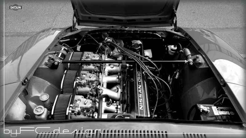
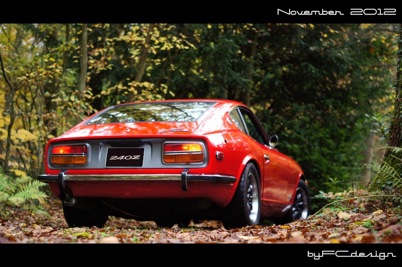
Datsun 240z with L28 & 3x 40 DCOE, MJLJ w/ TPS

Show off your Megajolt installations, vehicles and action shots here!

Moderators: JeffC, rdoherty, stieg, brentp

Lazeum
Posts: 74
Joined: Mon Sep 17, 2012 3:03 pm
Location: Paris, France

Datsun 240z with L28 & 3x 40 DCOE, MJLJ w/ TPS

Post by Lazeum »

Here’s my car : ’72 Datsun 240z with 2.8L L28 engine coming from a 280zx.
I'm converting it to Megajolt this winter during snow (& salt) season.
I've tried to be exhaustive with my presentation.

Only big advice I've got: Get good crimping tools! You must invest in one pair of pliers at least. I've got 3: one for moley pins, 2 for regular flat pins.
I would discourage anybody who would intent this process with regular pliers.

Image

Image

Image


There’re a lot of stuffs made on the engine:
- Head milled, ported, polished, unshrouded, combustion chambers CC’ed, new valve seats, Dual lub systems (internal in cam + spray bar)
- Cam with asymmetrical profile from Rebello Racing with adequate springs, rockers, etc.
- Bottom end is new also with new pistons, rings, bearings, etc. Compression ratio is around 9.0:1 / 9.5:1.
- 3x Weber 40DCOE with ported intake. Each runner is linked with the others with a canal to balance pressure between them.
- 6-2-1 exhaust header + 2,5” exhaust
- Soon to disappear Mallory Unilite distributor :)

I’m in process of converting the car. Wiring is almost done, I now need to focus on mechanical installation.

I’ve chosen to run MJLJ with TPS option but I don’t exclude to convert it to MAP later.

For TPS, I’ve picked one up from a BMW 323ti (E36). The TPS is not having any spring loaded control, its shape for the shaft is easy to reproduce (a round ø8mm shape with one flat) & it is easy to get at any junkyard. Only concern would be that it is not water tight. I got it in Europe for 15€ with the entire throttle body (people get rid of it for better 325i unit)

I also got the one from Autosportlabs webshop but it is big, spring loaded with complex shaft print, so I won’t use it after all.

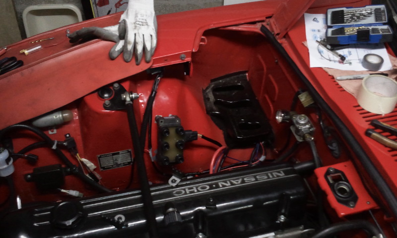
Regarding install, I’ve installed MJLJ box on the sidekick panel on passenger side with a relay support + fuses.

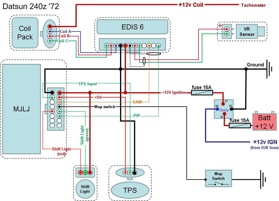
I’ve made a wiring diagram based on info from the “how to” section. Only difference is the way I expect to power up the EDIS coils. I’m going to plug the +12V source from the coil + side since my tach is triggered this way.
Image

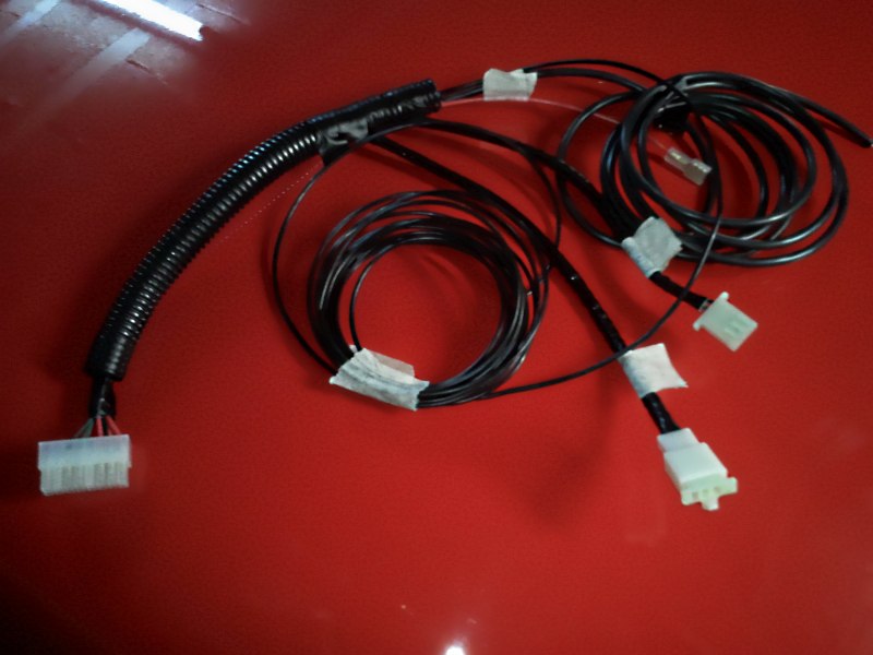
All wires are crimped with proper tools. When wires needed to be connected together; I’ve twisted them together, soldered them & protected them with shrink tubes.
Wires are all protected with high temp hoses under the hood.
Image

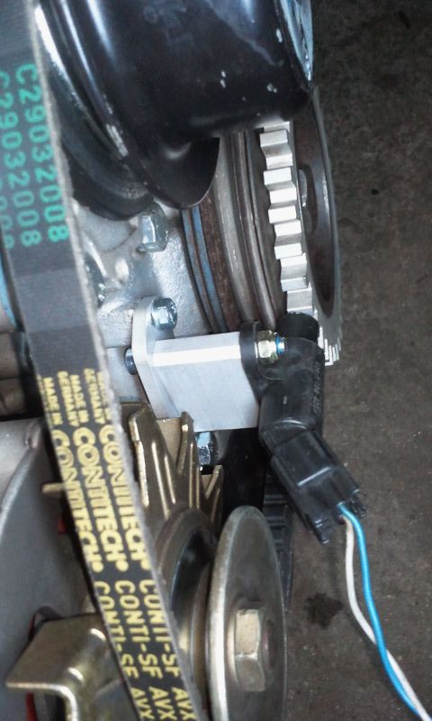
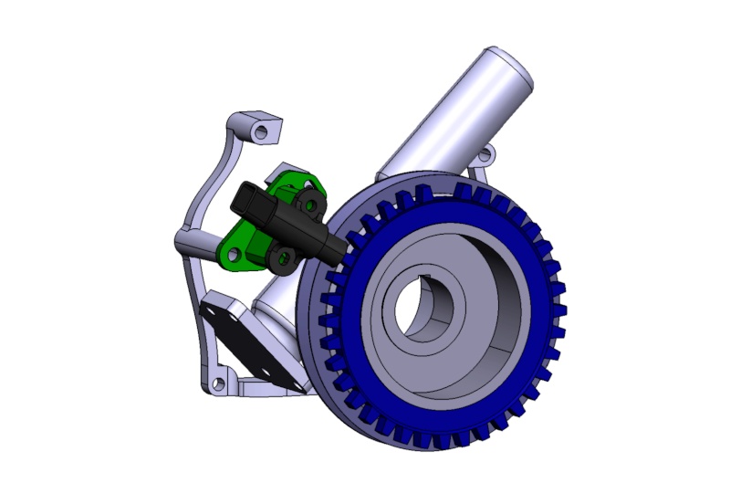
For VR sensor, I’ve made a CAD model of the front of the engine to design a support. Support, in aluminum, is made with a CNC machine. I’ve taken into consideration some margin for adjustability.
The drawback from the support is I need to ditch the stock fan & go with e-fan instead. I wanted to do it anyway so I did not bother…
Image

Image

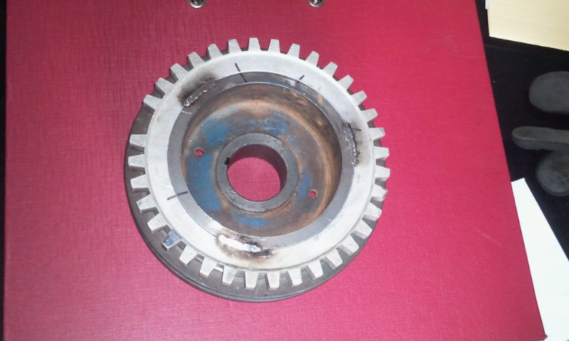
36-1 wheel is coming from the EDIS car donor. Crank damper has been machined to be slightly smaller than the wheel. I cannot feel any play but wheel can rotate freely around the pulley.
The plan is to install the VR sensor, get the wheel in front of it accordingly, get a mark done & spot weld the wheel in place (hopefully the weld will not hurt the rubber, I’ll be careful about that).


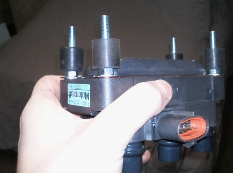
EDIS coils have some rubber pads installed to avoid vibrations. Pads also raise the coils allowing me to get it install on a flat surface without any specific support. Pads are male/male type with ø20 OD. I had to make a thread on each Coil support hole to make pads fit.
Image

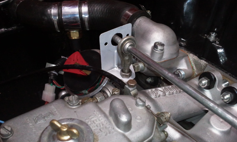
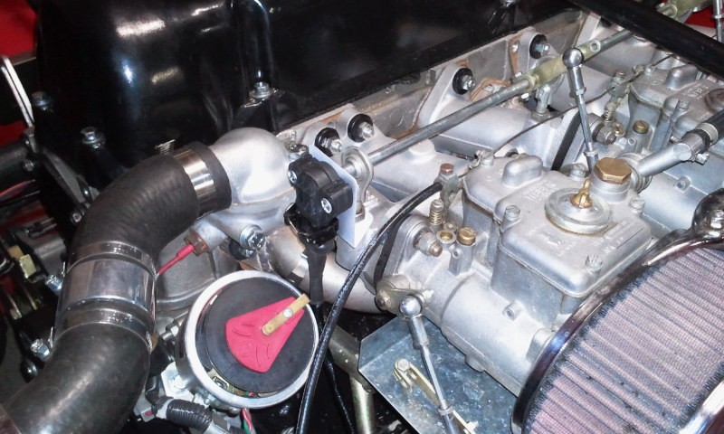
TPS will be mounted on carbs rod linkage instead on carb shaft. My DCOE are the old style, there’s no hole on housing to install easily a support for TPS.
Drawback with the way I expect to install TPS is that I won’t have 90° angle between idle & WOT but around 45-60°. Hopefully TPS resolution / sensitivity will be sufficient.
The support will be a very simple steel plate design bent, nothing really fancy. Still need to design it and make it.

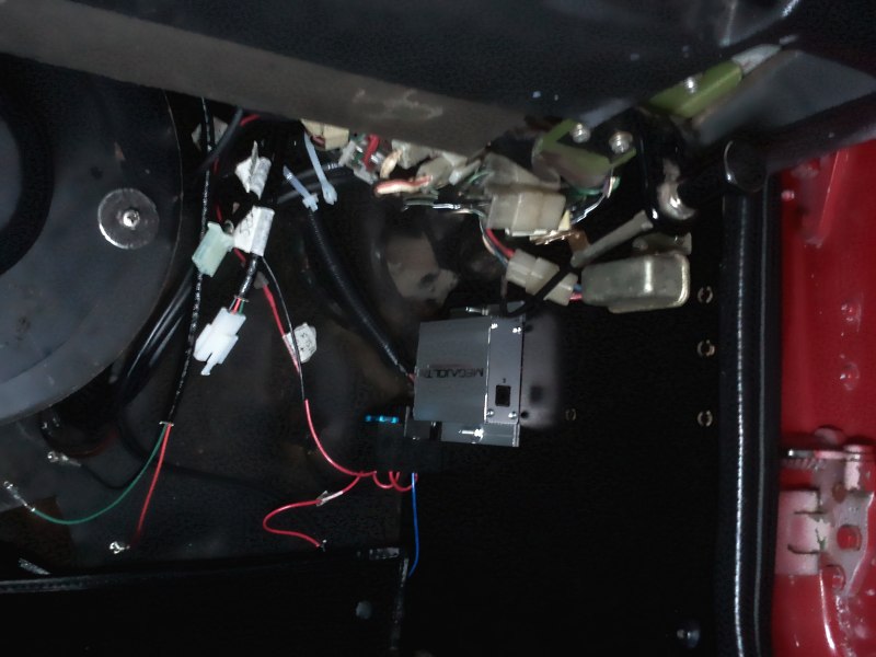
To finish the first post, here's how my install looks like for now (or almost, wires have been setup, I don't see anything anymore from the driver side)
Image


The next steps would be to try the new support, check 36-1 wheel position, get the wiring finished under the hood and install EDIS components.
Mathieu

Lazeum
Posts: 74
Joined: Mon Sep 17, 2012 3:03 pm
Location: Paris, France

Post by Lazeum »

During vacations, I was able to finish the project. I haven't started the car yet but the system reacts with the sensor & everything is done.

Here are some pictures of the sensors & other EDIS components installed inside the car.

The support made for VR sensor is installed & working as it should.

Image

The 36-1 wheel has also been welded to the crank pulley. I was afraid about heat that could have damaged the rubber part of the damper. So I've been careful about that. The wheel & damper are massive enough to dissipate the heat enough without any problem. The part was barely hot to the touch.
I still need to sandblast the part & paint it to look good before final installation.

Image

I also installed the coils on the fender of the car. The location chosen is the one where the 4 points from the coils are in contact with the car body. So it is not 100% straight but it is the only way without any extra support to locate it properly.

Image

To power the coils, I took a 12V source from the original coil. To leave the original harness in place, I soldered an extra wire under the dash. The wire is Black w/ white stripe.

Finally I've finished TPS install with a support made in 0.5mm thick steel plate.

Image

Image

When I plugged my laptop to the MJLJ, I can read what's inside, I can calibrate my TPS to read 0 / 100% (but I don't see the area moving that much on timing map - engine might need to run for that) & setup everything.

I need custom spark plug wires to finish the install which is now complete.
Mathieu

Lazeum
Posts: 74
Joined: Mon Sep 17, 2012 3:03 pm
Location: Paris, France

Post by Lazeum »

One side comment: I just realize by having my coil pack plugged the way it is (right from the tacho instead of coming from MJLJ), the rev limiter from the MJLJ may not operate since it is not powering the coils...

Ultimately, it seems I should put the tacho in between MJLJ & the coilpack to get rpm signal working.
Mathieu

fenderstrat536
Posts: 11
Joined: Thu Oct 21, 2010 7:50 am

Post by fenderstrat536 »

I would set this up as having the 12v feed for the coil coming from the relay where the EDIS module and the MJ are powered from.
For the tach to function it will need to use the tech output from the MJ or an aggregated signal from the coil using something like the tach adapter http://www.autosportlabs.net/TachAdapter
Also make sure you have 12v feeding that relay even during cranking

Lazeum
Posts: 74
Joined: Mon Sep 17, 2012 3:03 pm
Location: Paris, France

Post by Lazeum »

Thanks for the tips :wink:
Somehow I need to run the coils from the MJLJ unit since I have a hardrev limiter built inside already.

Regarding Tacho, I purchased the converter but I found out my tach is an "old style" tach working with voltage pulses, not amps so tach needs for sure to be in between 12v source & coil.
If that does not work, next option would be to swap my tach with a newer style & use the MJLJ tach output + converter.

I haven't started the car yet, first trials will tell me if it works. I'm quite anxious :)
Mathieu

Lazeum
Posts: 74
Joined: Mon Sep 17, 2012 3:03 pm
Location: Paris, France

Post by Lazeum »

Car started for the first time with no distributor this past weekend!

I've faced some issues that were easy too fix since they have been fixed by other members :

- No sparks - VR sensor wires were not plugged the proper way. I have attached blue on gray & gray on blue. Since sensor & EDIS controller were coming from the same donor, the right way was blue on blue, gray on gray. I knew immediately what went wrong as soon as I've noticed no spark, it was easy to fix.
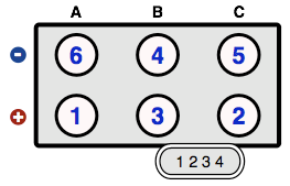
- Backfires thru carbs without starting - I knew timing was off. I got confused with EDIS firing order A-C-B. Since nothing was written on the coils, I've also mixed up A with C & C with B, etc... it was a mess. For the record, here the correct diagram that works, found on the forum:

Image

Once those 2 items were sorted, the car started right up! it still pops from time to time but I've only run it for 20 seconds max. I was in the garage (closed), roads are covered with salt. Tuning will be for spring.

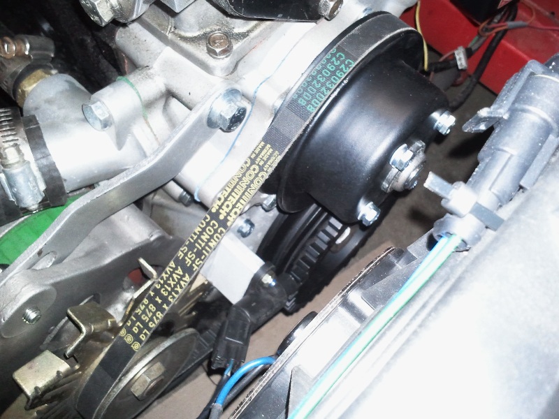
Picture of the VR sensor & its support, I could have done it 1 or 2 mm taller (0.040 -0.080") , it would have put the sensor right in the center of the wheel. It is still in front of it though so I'm not concerned.
Pulleys have been sandblasted and painted to look new.

Image
Mathieu

dr.occa
Posts: 243
Joined: Fri Feb 23, 2007 10:52 pm
Location: TX

Post by dr.occa »

I love your TPS mount! Simple but effective!
AUTOSPORTLABS
NonStop Tuning
www.86garage.com

"Poverty is not a virtue."

Lazeum
Posts: 74
Joined: Mon Sep 17, 2012 3:03 pm
Location: Paris, France

Post by Lazeum »

Thanks!
The outcome looks simple but I've tortured my brain to find the most appropriate way to finally end up with what you can see (it took me 4 attempts to make the part fit with the right geometry though).
Only irreversible damage done is on the carb linkage rod that was filled a little to create a flat to match TPS sensor pattern.
Mathieu

Lazeum
Posts: 74
Joined: Mon Sep 17, 2012 3:03 pm
Location: Paris, France

Post by Lazeum »

I've started tuning stage :D

The car runs good for now but I haven't driven it yet.
I'll post my progress whenever it happens.

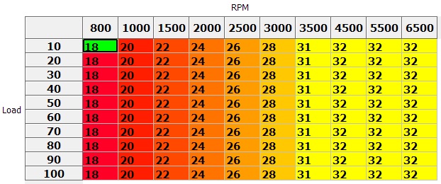
So far, my first TPS timing map. I've ignored TPS correction & run the car only in "2D" mode. This was how the car run before MJLJ ignition with regular distributor without vacuum (Mallory Unilite)

Image

I'll focus first on 2D map. Once it will be good enough, I'll switch to "TPS tuning".
I know at some TPS level, engine efficiency will max out, so some cells will remain untouched. Below the threshold, timing will have to be increased. Here's the plan for the future.
I don't know yet the exact shape of the blue limit on the picture below. I'll have to find out with the car.
I expect some carb tuning to happen as well once I'll start messing up with low load / high timing for cruising.

Image

I'm sharing for people to learn but also for the ones that would want to criticize my plan - I'm very open to suggestions :wink: Please comment if you'd like.
Mathieu

brentp
Site Admin
Posts: 6282
Joined: Wed Jan 24, 2007 6:36 am

Post by brentp »

Gorgeous build, and I love the color.

Next time we are in Paris I would love to meet you in person! :)
Brent Picasso
CEO and Founder, Autosport Labs
Facebook | Twitter

brentp
Site Admin
Posts: 6282
Joined: Wed Jan 24, 2007 6:36 am

Post by brentp »

Is it possible to get a copy of your CNC crank trigger bracket? We have a 240z we want to convert to crank-fired ignition as well.

Let us know!
Brent Picasso
CEO and Founder, Autosport Labs
Facebook | Twitter

Lazeum
Posts: 74
Joined: Mon Sep 17, 2012 3:03 pm
Location: Paris, France

Post by Lazeum »

Just tell me the format and I'll proceed.
I will only do it on wednesday the earliest, I don't have access to my PC for now.

...and I'll be glad to meet you if you're around town. The Z is 35km away from Paris though (in the West side).
Mathieu

brentp
Site Admin
Posts: 6282
Joined: Wed Jan 24, 2007 6:36 am

Post by brentp »

Actually, I was meaning a physical copy of the aluminum parts. :) Can we purchase those somewhere?
Brent Picasso
CEO and Founder, Autosport Labs
Facebook | Twitter

Lazeum
Posts: 74
Joined: Mon Sep 17, 2012 3:03 pm
Location: Paris, France

Post by Lazeum »

Actually, I've made my own CAD design & I've asked a prototype supplier at work to make it as a side project :roll:
For your info, with CNC program and super friendly price, I've paid 100€ for such bracket.

Anyway, design has been done to make it easy (= quick since it was to help) to produce. The only required tool to make this part is a tower drill to make straight & parallel holes. The plate can be done with regular tools (it is a rectangular shape with blend radii. bean shape holes can be done with a tower drill also.

If you want something as clean as my bracket, you need to find somebody with CNC machine for the plate. The hard part is the programming activity. I can provide you drawings if you need them (they are already available on hybridz)
Mathieu

brentp
Site Admin
Posts: 6282
Joined: Wed Jan 24, 2007 6:36 am

Post by brentp »

Hi- yes, thank you. could you email here or zip them up as a forum attachment?

Thank you!

Post Reply