Hi community,
I am currently installing the Megajolt in my X-Flow powered Caterham 7.
The engine is a 1700 Ford X-Flow with a Kent 244 cam running on dual Weber DCOE 45s.
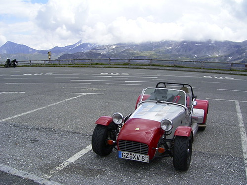
Here is a shot of the car while it was still running....
Caterham 7 von gnulpt auf Flickr
I will post new images and descriptions as I go along, so please bear with me if it takes a while.
Klaus
Munich
Germany
Caterham 7 Ford X-Flow 1700
Moderators: JeffC, rdoherty, stieg, brentp
Distributor Blanking Plug
So we get started by stripping the engine.
Of course the distributor was removed...
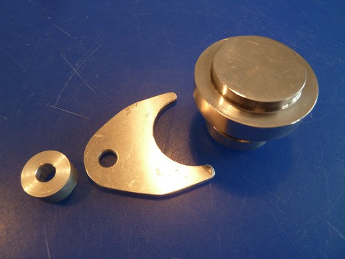
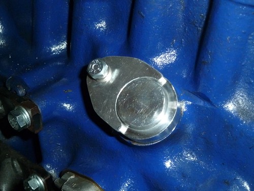
But now an ugly hole is in the block. So I needed a blanking plug. There are many on the market but I ordered mine from Trigger Wheels when I also ordered the Megajolt from them.
You need to get the 27mm A+ series type. Unfortunately it looks like all of those are designed to use the original dizzy clamp to hold them down in the engine block.
I did not like the looks of the clamp and therefore manufactured a small "fork" out of aluminium an a spacer that holds the plug in place.
Here are some pictures...
The parts
Installed in block
Last edited by gnulpt on Thu Jun 27, 2013 9:27 pm, edited 1 time in total.
2 ltr Pinto in a Mk2 Escort
Hey gnulpt,
Im trying to do the same to my escort with a 2 ltr pinto. how difficult is this system to instal where do you even start? any info will be appreciated.
Thanks
Im trying to do the same to my escort with a 2 ltr pinto. how difficult is this system to instal where do you even start? any info will be appreciated.
Thanks
-
- Posts: 2
- Joined: Sat Jan 29, 2005 12:36 am
- Location: surrey uk
Re: 2 ltr Pinto in a Mk2 Escort
G'day Ramo!Ramo wrote:Hey gnulpt,
Im trying to do the same to my escort with a 2 ltr pinto. how difficult is this system to instal where do you even start? any info will be appreciated.
Thanks
Sorry for the late reply.
The install should be pretty straight forward. There are a lot of projects around where you will see how other people did it...
However, here is some advice:
1) First, draw a schematic of how you plan to wire the system in your car. While drawing it, include all the connectors you might need. Also think about how you will wire it into the vehicle power. You will need fused power, where will you get it from... need an extra fuse?
2) Check your car where you want to install all components.
3) Make a list of all the parts you need.
4) Start to order some parts. I started with the MJ, VR sensor and coil pack. Once you got them place them in the car to see where you really want to mount them.
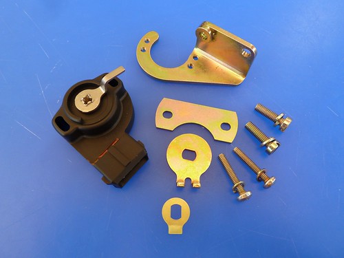
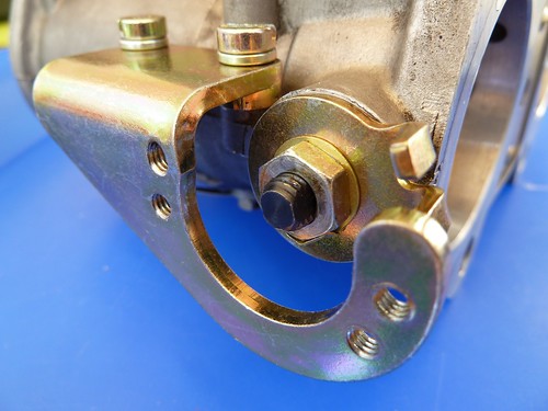
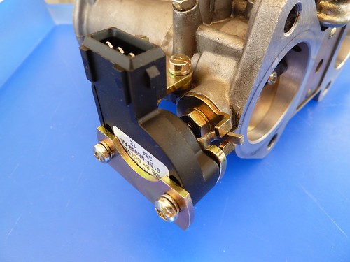
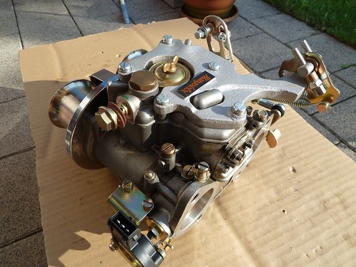
5) Funny enough, I found mechanical parts the hardest stuff. If you have a TPS install, you will need to mount the TPS to the carb. I simply purchased a finished kit for the DCOE. Easy plug and play....
The really tricky one is the trigger wheel and the VR sensor. Making the VR sensor bracket is a quite tricky if it should look neat. I decided to make my own three months ago and still working on it.... lesson learned, I would now purchase a finished product.
6) Once you are shure where you would like to install everything, get all parts that you need to finish the install.
e.g. Connectors, wiring for the harness, isolation tape, shrink tube, fuse holders ect.
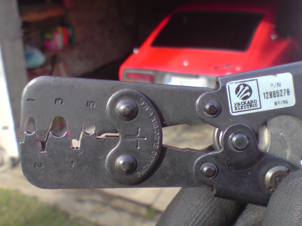
Do not forget to get a good crimp tool!
7) Only if you have all the bits and pieces, start the install. It took me 4 weeks to have some custom ignition cables being made. Remove everything from the car that is not longer needed. So the car will not longer run until it is all in.
I am still at 7).... so I am entering nebulous territory as I write...
Hope this helps!
Klaus
That's a good write-up
Get absolutely some good weathertight connectors for everything that could get wet/moisture under the hood.
I've probably spent more time planning everything than doing the job done. Get organized, use colors for wires and as Klaus said, get some good crimping tools.
Don't use pre-insulated connectors, use non insulated ones & put some shrink tube around after. It looks x10 times better this way. It is also much easier to check if connection is tight.
You need one with a "B" shape once closed. Here's the one I used. See the shape of the features on the bottom jaw.
Mathieu
Trigger Wheel
Some more progress...
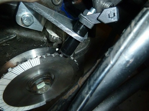
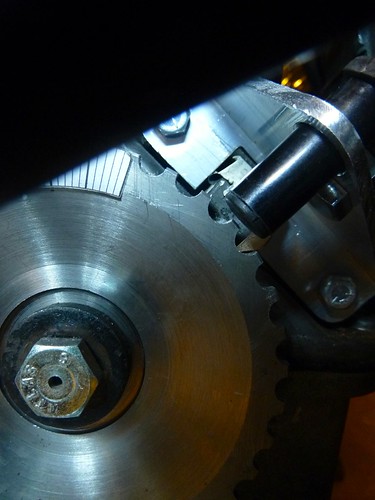
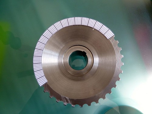
Instead of using a universal trigger wheel that bolts to the original pulley of the x-flow, I decided to get a machined pulley that has the trigger wheel built in.
I have sourced it from QED Motorsport.
It is the Lotus Twincam crank pulley with the 36 teeth machined in.
The trigger pulley is universal in a sense, since it has all 36 teeth. So once I have decided where the VR-sensor is positioned, I can cut off one tooth to make the missing one...
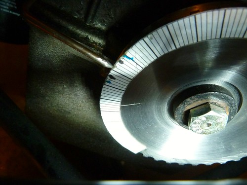
Instead of using a degree wheel, I decided to print a degree scale on paper and stick it onto the pulley... cheap and cheerful....
VR-Sensor Bracket
Next on the agenda was to build a bracket for the VR-sensor.
First I had to find a convenient place on the engine block where I could install the bracket without too much hassle.
I had a look at the Weber crank TDC trigger kit. This mounts nicely near the TDC marker on the engine block, so I decided to do the same.
Because the trigger wheel is an integral part of the QED pulley, I had to come up with a bracket that would exactly position the VR-Sensor over a tooth when at TDC.
So I did the following:
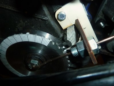
1) Build a wooden mock-up of a small plate that would clear the TDC marker on the engine block and use two bolts with spacers in order to bolt that plate to the block.
2) Build a small wooden plate with a slot for the VR-sensor. This plate goes perpendicular to the base plate...
I also installed a bolt that has about the same diameter as the VR-Sensor in the slot. I drilled a hole in the center of the bolt to accept a thicker wire for the following step.
3) Next I drilled a pilot hole into an old pulley bolt and used this to attach the pulley to the crank.
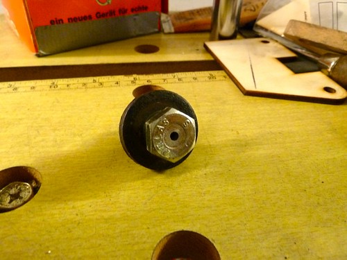
4) Then I bent some wire into an L-shape... get the idea?
This wire slides into the bolt in the wood plate an into the pilot hole in the crank bolt.
5) Now it is time to put the engine at TDC...
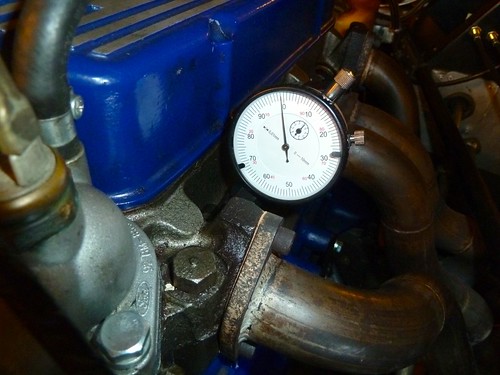
I used a dial gauge in cylinder one. Using the good old finding TDC procedure (google it up...) I slowly turned the engine over a couple of times, dialing in the same gauge value before and after TDC, marking the points on the timing disk that I glued to the pulley. TDC is then the exact center between the two marks.
6) Back to the VR-Bracket...
With the engine at TDC, I now inserted the L-shaped wire into the pilot hole.
Now, I simply needed to rotate the whole assembly around the pilot hole and position everything exactly over a tooth...
I just needed to mark where everything needed to be....
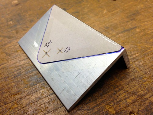
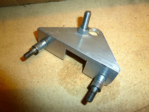
7) With everything marked up, I could now do some cardboard to make the final shape and transfer this over to a 5mm aluminium L-shaped material.
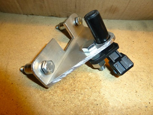
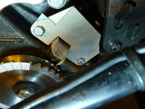
8) Just some small saw, drill and file action, and here is the bracket in all its beauty...
First I had to find a convenient place on the engine block where I could install the bracket without too much hassle.
I had a look at the Weber crank TDC trigger kit. This mounts nicely near the TDC marker on the engine block, so I decided to do the same.
Because the trigger wheel is an integral part of the QED pulley, I had to come up with a bracket that would exactly position the VR-Sensor over a tooth when at TDC.
So I did the following:
1) Build a wooden mock-up of a small plate that would clear the TDC marker on the engine block and use two bolts with spacers in order to bolt that plate to the block.
2) Build a small wooden plate with a slot for the VR-sensor. This plate goes perpendicular to the base plate...
I also installed a bolt that has about the same diameter as the VR-Sensor in the slot. I drilled a hole in the center of the bolt to accept a thicker wire for the following step.
3) Next I drilled a pilot hole into an old pulley bolt and used this to attach the pulley to the crank.
4) Then I bent some wire into an L-shape... get the idea?
This wire slides into the bolt in the wood plate an into the pilot hole in the crank bolt.
5) Now it is time to put the engine at TDC...
I used a dial gauge in cylinder one. Using the good old finding TDC procedure (google it up...) I slowly turned the engine over a couple of times, dialing in the same gauge value before and after TDC, marking the points on the timing disk that I glued to the pulley. TDC is then the exact center between the two marks.
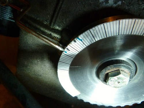
6) Back to the VR-Bracket...
With the engine at TDC, I now inserted the L-shaped wire into the pilot hole.
Now, I simply needed to rotate the whole assembly around the pilot hole and position everything exactly over a tooth...
I just needed to mark where everything needed to be....
7) With everything marked up, I could now do some cardboard to make the final shape and transfer this over to a 5mm aluminium L-shaped material.
8) Just some small saw, drill and file action, and here is the bracket in all its beauty...
-
- Posts: 30
- Joined: Sun Dec 01, 2013 10:18 pm
- Location: Belgium