
Hey guys! I am new to the forums as I am currently in the works of adding megajolt to my 1983 BMW e21 turbo group 2 project. I started off by bench testing my whole setup to see how things work and such. I didn't have a spare trigger wheel, so I used a rear sprocket off a mini bike attached to a power drill. I wired everything up and connected it to my 12v power supply. As I started to turn the drill, the spark plugs fired for a second or two and then stopped. After trying again multiple times, they would spark randomly and only for a second or two. I decided to connect it to the car as it was on the bench test and I am getting NO SPARK.
I have done some testing ...
I have 12v to edis unit and coil pack with ignition ON.
I have 9v to edis unit and coil pack when cranking.
checked vr sensor for metal crap at end and it was clean.
checked vr sensor resistance between pins and got 380 ohms.
checked coil pack resistance between pins 1-2 & 2-3 and got 1.9-2.0 ohms (I recall reading that this resistance should be between 0.4-0.6 ohms ... could this be an issue?)
From the spark plugs sparking for a few second or so during the bench test, this should mean that the vr sensor wiring is the correct polarity, right?
anybody have an idea on what the issue could be? Thank you!!!!
Another no spark situation
Moderators: JeffC, rdoherty, stieg, brentp
-
bassboy3313
- Posts: 13
- Joined: Sun Oct 20, 2013 7:53 pm
- Location: Wisconsin, USA
-
bassboy3313
- Posts: 13
- Joined: Sun Oct 20, 2013 7:53 pm
- Location: Wisconsin, USA
-
bassboy3313
- Posts: 13
- Joined: Sun Oct 20, 2013 7:53 pm
- Location: Wisconsin, USA
-
bassboy3313
- Posts: 13
- Joined: Sun Oct 20, 2013 7:53 pm
- Location: Wisconsin, USA
Well, I went ahead and rewired everything for the edis since the PO did some of the wiring and at this point I didn't trust it. I benched tested it all and the plugs didn't spark again. Gggrrr!!! I then remembered that the most common reason was the vr sensor wires being backwards. I reversed the wiring and I got spark on all plugs. SUCCESS!! I then moved the whole thing out to the car. I used the stock ignition coil power as the positive and used the car body as the ground. I cranked over the engine and all 4 plugs sparked again. MORE SUCCESS!!! Now to put everything together permanently and see if the engine fires up. Cross your fingers!!!
thats good. let us know what happens.bassboy3313 wrote:Well, I went ahead and rewired everything for the edis since the PO did some of the wiring and at this point I didn't trust it. I benched tested it all and the plugs didn't spark again. Gggrrr!!! I then remembered that the most common reason was the vr sensor wires being backwards. I reversed the wiring and I got spark on all plugs. SUCCESS!! I then moved the whole thing out to the car. I used the stock ignition coil power as the positive and used the car body as the ground. I cranked over the engine and all 4 plugs sparked again. MORE SUCCESS!!! Now to put everything together permanently and see if the engine fires up. Cross your fingers!!!
-
bassboy3313
- Posts: 13
- Joined: Sun Oct 20, 2013 7:53 pm
- Location: Wisconsin, USA
-
bassboy3313
- Posts: 13
- Joined: Sun Oct 20, 2013 7:53 pm
- Location: Wisconsin, USA
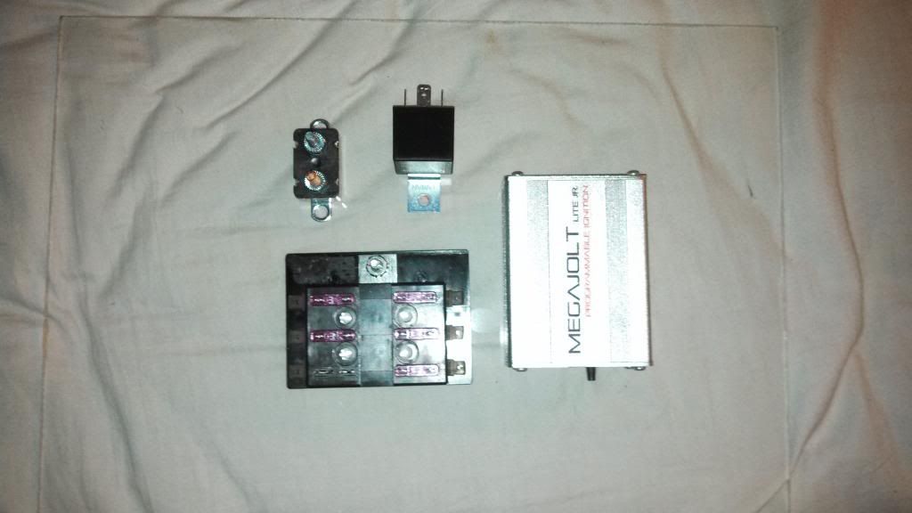
I decided to go with a separate fuse panel and for the EDIS, Megajolt (MJ), and throw the gauges on it too for good measure. Most of it will be mounted in the glovebox except the EDIS module and coilpack, obviously. I used a spare sheet of plexi that I had laying around and mounted the circuit breaker, relay, fuse panel and MJ with 3M tape.
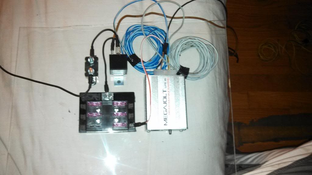
I then went ahead and wired everything up. I decided to take the constant power and ground from the glovebox flashlight circuit since I dont have the flashlight anyways. Turns out that some female bullet connectors fit perfectly on the pins of the flashlight circuit. All-in-all I think it looks great and of course, works like a charm.

I then went ahead and wired everything up. I decided to take the constant power and ground from the glovebox flashlight circuit since I dont have the flashlight anyways. Turns out that some female bullet connectors fit perfectly on the pins of the flashlight circuit. All-in-all I think it looks great and of course, works like a charm.
