plenum and vaccum hose design for individual runners
Moderators: JeffC, rdoherty, stieg, brentp
plenum and vaccum hose design for individual runners
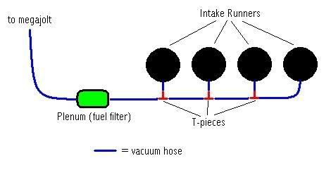
would this work?
or would the unequal lengths and the fact that the hoses join so close to the runners create a vaccum problem?
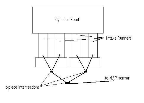
or would an idea like this work better?
also, i still need to know what size hose is used for the MAP sensor in the megajolt ECU
thanks for any help!
Regards,
Julian
or would the unequal lengths and the fact that the hoses join so close to the runners create a vaccum problem?
or would an idea like this work better?
also, i still need to know what size hose is used for the MAP sensor in the megajolt ECU
thanks for any help!
Regards,
Julian
Hi Julian,
Both hose configurations should be fine. What is more important is the mini-plenum to smooth out the pulses.
We have a little write up on the subject here: http://www.autosportlabs.net/MJLJ_V3_ve ... _.28TPS.29
Regards,
Both hose configurations should be fine. What is more important is the mini-plenum to smooth out the pulses.
We have a little write up on the subject here: http://www.autosportlabs.net/MJLJ_V3_ve ... _.28TPS.29
Regards,
I am just about to fit my system to an A series engine (siamesed inlet ports and twin SU carbs) with connected pipes and a plenum (around 120cc) as recommended.
I am just a little concerned about the filling and emptying time during rapid throttle changes with this plenum.
Anybody have any experience?
Thanks
I am just a little concerned about the filling and emptying time during rapid throttle changes with this plenum.
Anybody have any experience?
Thanks
I had a muck about with your image, Brent, and came up with this option (don't want to tread on any toes though ). Would this offer any advantage over the other arrangement? The reservoir would have a union per runner, and basically replaces the tee-pieces. If this format was employed it'd most probably be easiest to mount it locally.
As for the filling and emptying, on an NA car such as a twin-SU'd Mini, from the moment the engine cranks the reservoir would see negative pressure, and this vacuum would only vary, rather than fill and empty and at worst would take split-seconds to catch up. Provided the reservoir is not overly large, there'd be no problem at all - between 1/4 and 1/3 of engine capacity would be perfect.
- Attachments
-
- Individual signals to reservoir.
- Adapting_map_sensor_for_multiple_runners.png (14.19 KiB) Viewed 58037 times
In further thought, I think your proposal has the edge in being more 'technically correct'- I'm trying to picture what the individual runners are doing on the 4 parts of the otto cycle. I'd like to replace the wiki image with what you updated, I hope you don't mind?
in any case, while one runner is drawing vacuum, another runner has it's intake valves closed, so atmospheric air pressure would travel from this runner towards the runner that's drawing vacuum. I think your modification has this path going through the plenum and seems more correct- but I'm not prepared to do the math on this. Perhaps direct measurement of both approaches might be interesting???
Good thoughts.
Last edited by brentp on Tue May 08, 2007 6:30 pm, edited 1 time in total.
I've added the alternate approach to the wiki:
http://www.autosportlabs.net/MJLJ_V3_ve ... _.28TPS.29
By the way, wiki pages are open to all for modifications- you're welcome to make corrections or additions!
http://www.autosportlabs.net/MJLJ_V3_ve ... _.28TPS.29
By the way, wiki pages are open to all for modifications- you're welcome to make corrections or additions!
Julian!
Since you're in the process of building this out, would you be willing to try the different approaches and report back?
Some interesting data points would be:
- what the vacuum is at idle
- how smooth the vacuum reading is
You could perform a short datalogging session using the software, or; you could simply observe with a vacuum gauge if you have one. If you perform a datalogging session you could attach the output files to this thread and we could all analyze it.
What do you think? Do you have time in your schedule to help us out?
I did some quick logs with no plenum, a 140cc plenum and a 60cc plenum.
I rigged up a temporary TPS on the twin SU carbs of the A series just to get an idea of what the throttle is going. (drive to the TPS is a bit indirect as the float chambers are in the way which is why I went for a MAP version of the MJL)
I did some no load throttle blips and WOT runs.
It seems that (as expected) the larger plenum damps out the pressure well but causes a bit of a delay in the signal.
These logs were unfiltered 100Hz signals using a Marelli MAP sensor to measure the pressure from a 'T' of the two runners of the inlet manifold.
I still need to do a bit more but I think I might go for the 60cc plenum (which is about halfway in terms of response between nothing and the 140cc plenum)
Quite intersting to see what is going on anyway.
- Attachments
-
- no plenum multi blip.JPG (99.42 KiB) Viewed 57923 times
-
- no plenum wot.JPG (91.06 KiB) Viewed 57925 times
-
- 140cc plenum multi blips.JPG (93.78 KiB) Viewed 57928 times
Just forgot to add that each connection to the intake manifold had a 2mm bore (the old advamce/retard fittings) which will damp the signal out a little itself. The pipework to the plenum was either 3/16" or 4mm bore (can't remember) and about 1m long (should really try to reduce it but the MJL has will have to be mounted nearly that far away)
I will try to do a little more logging with the 60cc plenum.
My last attempt was aborted due to the vacuum pipe dropping onto the exhaust manifold!!
I will try to do a little more logging with the 60cc plenum.
My last attempt was aborted due to the vacuum pipe dropping onto the exhaust manifold!!
this makes very interesting reading. jst wondered if anyone has tried or thought of a vacuum damping plenum that was used on a production car?? i know lotus had the same trouble when the motorsport elise started running on tbi, they developed a little sphere that was aprox 2" in diameter that sat half way between the inlet manifold and the ecu! i've seen pictures somewhere on the web before but i can find them at the mo! if memory servs they used a sphere for a reason!
DO SOMETHING SILLY, TURBO AN 1100CC METRO
2" sphere is about 65cc interestingly!
Can't think of any obvious advantage over any other shape (as long as the aspect ratio is not daft) except strength but that can't be too imortant in this application. I would have thought any difference would be secondary to plenum volume anyway.
A £1.50 fuel filter seems to be a good solution at the moment!