VR sensor installation problems
Moderators: JeffC, rdoherty, stieg, brentp
VR sensor installation problems
I have set up the sensor to be 90 degrees from the missing tooth. When I put on a timing light I look to be 1 tooth adrift i.e the timing mark on the pulley shows counterclockwise of the timing pointer by about 1 tooth (10 degrees) this is with 10 degrees set into the timing light. The odd thing is I have to dial in nearly 60 degrees to get the timing marks to line up. Is there something about the wasted spark system that upsets timing lights (Gunson with dial in-able advance)? I have wired up the plugs as per the coil block numbering i.e no. one plug to '1' no.2 plug to '2' etc. I presume this is correct? This is my second attempt at putting the sensor in and I'm getting very frustrated . The engine starts ok so I'm somewhere near! Maybe I need to make my teeth profile deeper. I've had the teeth machined into the pulley and have alrwady deepened the 'dips' with a Dremel. Maybe I need to take some more out.
I have not got mine working yet but this how deep they are: http://s73.photobucket.com/albums/i229/ ... mview=grid . I notice you dont have any adjustment, are you sure the missing tooth is in the correct position?
I see you have machined your pulley to accept a trigger wheel. Maybe I should have done the same. I can't remove the pulley ow unless I take the engine out, but I can get a Dremel to it if I'm careful.
I've double checked the TDC position and have the sensor 9 teeth away from the notch give or take a fraction of a tooth. The sensor is 1 to 1.5mm away from the teeth. I have some adjustment in the sensor position. Will try again this evening.
I've double checked the TDC position and have the sensor 9 teeth away from the notch give or take a fraction of a tooth. The sensor is 1 to 1.5mm away from the teeth. I have some adjustment in the sensor position. Will try again this evening.
-
david jenkins
- Posts: 204
- Joined: Tue Feb 14, 2006 2:14 pm
- Contact:
I've just finished reprofiling the teeth on my pulley wheel. Now 3 to 4mm deep with a much squarer profile. There has been little improvement on the consistancy of the timing. Wandering about by 10 degrees or so. I have positioned the sensor so it's almost touching the pulley. I was expecting a solid 10 degree default timing. I'm somewhat disheartened by this. I will connect up the Megajolt control unit later this week to see if this makes any difference. I'm really running out of ideas as to why the timing is erratic, unless it is a duff EDIS unit. If things don't improve I'm tempted to get an Aldon distributor instead.
Haven't seen a picture of your trigger wheel yet, but a simple and safe approach is to emulate what the Ford engineers did for their OEM designs.
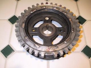
This is a Ford Escort trigger wheel adapted to a Toyota 4AG pulley. Note the depth and thickness of the teeth.

The timing should be rock solid at 10 degrees on EDIS alone- this indicates the EDIS module can accurately track the position of the crank shaft.
This is a Ford Escort trigger wheel adapted to a Toyota 4AG pulley. Note the depth and thickness of the teeth.

The timing should be rock solid at 10 degrees on EDIS alone- this indicates the EDIS module can accurately track the position of the crank shaft.
