Wiring it all in! Help...

EDIS and Megajolt installation related topics. Be sure to review the <a href="http://www.autosportlabs.net/MJLJ_V4_vehicle_installation_guide">Vehicle installation guide</a>

Moderators: JeffC, rdoherty, stieg, brentp

Mini1293
Posts: 51
Joined: Sat Jan 31, 2009 11:08 am
Location: Sussex

Wiring it all in! Help...

Post by Mini1293 »

Hi there...

Now iv more or less re-wired my car, i am ready to wire in my MJLJR and edis etc etc..

Iv been doing quite a lot of looking around on the net but cant find alot, so was hoping you lot can help me :)

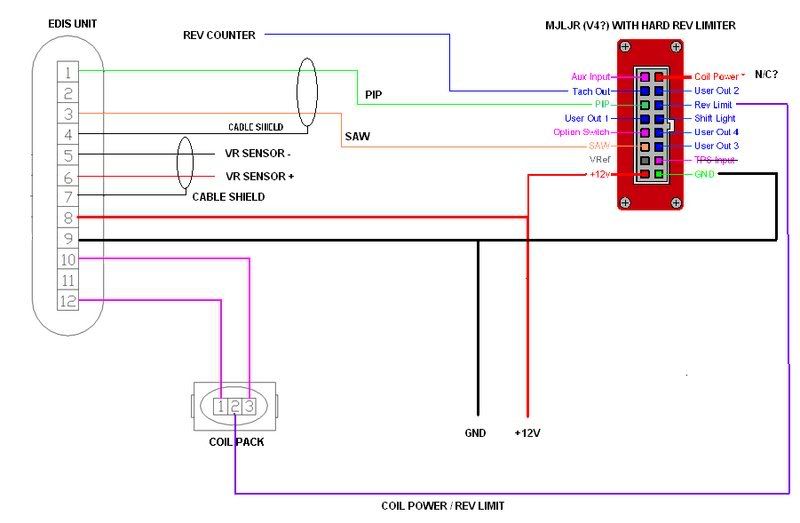
Iv found this... http://www.ken555.plus.com/gtm/edis_connection.html ... with the bottom diagram the one i think i need, iv got the hard rev limiter,
But, on the first diagram, you have to give the coil power... but the second one you dont, does it get it from the MJ then??

Iv also found this picture of the MJLJR pin out, now can someone explain each pin? As its got 2 +12v and 2 GND connections, also PGM 1 2 3and 4, and N/C.

Also if that diagram is right and i have to give power the the MJ and EDIS unit off the IGN switch site of the fuse box, what does it need, 10A?

Many thanks.
Attachments
PINOUT.jpg
PINOUT.jpg (63.66 KiB) Viewed 12897 times

Ken555
Posts: 92
Joined: Fri Sep 07, 2007 8:24 pm
Location: Aberdeenshire
Contact:

Post by Ken555 »

The 2nd diagram off my page that you are using, was with the rev limiter installed inside the main MJ case,
I cut the track to the rev limit connector on the big plug and used it as the output from the internal rev limiter to the coil.

So to answer your question, yes, the coil is powered by the rev limiter, which in turn is powered by the main MJ unit.

The rest of the questions are easier to explain.

The two 12v, any one can be used as they are common inside the unit.
Same goes with the ground connections.

The PGM connections are configured to give an earth/ground at set points on the rev range, from within the software, I use mine for gear change lights.
The same as the shift light connection.
http://www.ken555.plus.com/gtm/may08.html to see them

the N/C is Not Connected, so don't do anything with it.

brentp
Site Admin
Posts: 6292
Joined: Wed Jan 24, 2007 6:36 am

Post by brentp »

Important Note: If you have a V3 controller (green circuit board), then the plug wiring diagram is here:

http://www.autosportlabs.net/MJLJ_V3_ve ... guidelines
(note, this is looking into the unit)

Ken likely has a V2 controller, which has a different pinout than this.

Double check the version of your controller before proceeding!

Regards,
Brent Picasso
CEO and Founder, Autosport Labs
Facebook | Twitter

Ken555
Posts: 92
Joined: Fri Sep 07, 2007 8:24 pm
Location: Aberdeenshire
Contact:

Post by Ken555 »

brentp wrote:Important Note: If you have a V3 controller (green circuit board), then the plug wiring diagram is here:

http://www.autosportlabs.net/MJLJ_V3_ve ... guidelines
(note, this is looking into the unit)

Ken likely has a V2 controller, which has a different pinout than this.

Double check the version of your controller before proceeding!

Regards,
yes Brent I do have a V2 board, but the diagrams on my web page, never mentions MJ pin numbers just names.

In fact it's a modified version of those you have linked to.

Mini1293
Posts: 51
Joined: Sat Jan 31, 2009 11:08 am
Location: Sussex

Post by Mini1293 »

Heres a quick pics of my one i just took, I think il do a quick diagram in paint of how i think im going to do it and get you to look over it if thats ok?

Image

cheers

Ken555
Posts: 92
Joined: Fri Sep 07, 2007 8:24 pm
Location: Aberdeenshire
Contact:

Post by Ken555 »

Mini1293 wrote:I think il do a quick diagram in paint of how i think im going to do it and get you to look over it if thats ok?
Yes no problems

alexander
Posts: 246
Joined: Sat Jan 19, 2008 4:33 am
Location: sydney, australia.

Post by alexander »

Mini1293 wrote:Heres a quick pics of my one i just took, I think il do a quick diagram in paint of how i think im going to do it and get you to look over it if thats ok?
if it is of any help with laying out the diagram, this is what i did for the installation i am working on currently.
i used a free program called Gimp (almost as good as photoshop, and free!) to trim the images of the MJ and EDIS plug, and the Draw program in OpenOffice (almost as good as Microsoft Office, and free!) - like Paint, but more sophisiticated. had the advantage of having a grid onto which the lines naturally aligned themselves.

alexander
Attachments
jeep megajolt wiring diagram2.pdf
(76.42 KiB) Downloaded 677 times

brentp
Site Admin
Posts: 6292
Joined: Wed Jan 24, 2007 6:36 am

Post by brentp »

Mini1293 wrote:Heres a quick pics of my one i just took, I think il do a quick diagram in paint of how i think im going to do it and get you to look over it if thats ok?

cheers
It looks like you have a V4 controller- everything is wired internally for a clean installation.

Installing the rev limiter is very easy, simply follow the wiring instructions here:
http://www.autosportlabs.net/Hard_rev_l ... Controller

Regards
Brent Picasso
CEO and Founder, Autosport Labs
Facebook | Twitter

Mini1293
Posts: 51
Joined: Sat Jan 31, 2009 11:08 am
Location: Sussex

Post by Mini1293 »

thats a great help, thanks!

So if i have a V4 controller, do you have a link to the pin outs on that one, or is the one in my first post the right one?

Any hints on how to navigate arount the site would be good too ;)

many thanks.

Mini1293
Posts: 51
Joined: Sat Jan 31, 2009 11:08 am
Location: Sussex

Post by Mini1293 »

Just took some time and come up with this... hope its correct :)

Image

cheers.

Ken555
Posts: 92
Joined: Fri Sep 07, 2007 8:24 pm
Location: Aberdeenshire
Contact:

Post by Ken555 »

Mini1293 wrote:Just took some time and come up with this... hope its correct :)
One slight change needed, the power to the coil, needs to come from the COIL POWER connection at the top right, the one you have marked NC, this is assuming you have the rev-limiter installed inside the MJ box.
Attachments
MyMJLJRwiringdiag.jpg
MyMJLJRwiringdiag.jpg (43.82 KiB) Viewed 12783 times

Mini1293
Posts: 51
Joined: Sat Jan 31, 2009 11:08 am
Location: Sussex

Post by Mini1293 »

Ahh i see, and thats it? Nothing comes from the rev limit pin?

Also i just noticed, the edis box and the MJ has a rev counter output, what one am i better off taking it from.

cheers

Ken555
Posts: 92
Joined: Fri Sep 07, 2007 8:24 pm
Location: Aberdeenshire
Contact:

Post by Ken555 »

Mini1293 wrote:Ahh i see, and thats it? Nothing comes from the rev limit pin?

Also i just noticed, the edis box and the MJ has a rev counter output, what one am i better off taking it from.

cheers
yes thats all thats needed for a basic install, nothing from the rev limit pin.


I would guess the MJ unit for the Tach, it has a much improved Tach out now, but all depends on what you are feeding.
If It's an old Smiths Tach (I'm guessing based on Mini) then it would be worth trying both places, before making the loom up, you may need to use the diode trick from the coil pack if all else fails.

Mini1293
Posts: 51
Joined: Sat Jan 31, 2009 11:08 am
Location: Sussex

Post by Mini1293 »

Ok thats great, cheers. It is old mini clocks, but i dont think they are the smiths ones.

Iv been reading, and i quote... 'use 12 -14 gauge wire for the EDIS ground power and coil connections'... BUT, with the coil pack plug that iv got, theres no where near that size, its more like 1mm.
i cant get the plug apart so im going to have to join on the existing wires, so theres no use joining big onto small...

cheers

brentp
Site Admin
Posts: 6292
Joined: Wed Jan 24, 2007 6:36 am

Post by brentp »

Mini1293 wrote:Ahh i see, and thats it? Nothing comes from the rev limit pin?

Also i just noticed, the edis box and the MJ has a rev counter output, what one am i better off taking it from.

cheers
The rev limit output on the connector is the same as the connection on the inside of the unit, in case the user had an externally mounted rev limiter module.

*The 2nd diagram is correct: coil power comes from the "COIL POWER" on the connector.

Mini1293 wrote:Any hints on how to navigate arount the site would be good too
Just click the 'how to' link at the top of the page- all of the documentation is there, in wiki format. search and browse around. :)

Regards,
Brent Picasso
CEO and Founder, Autosport Labs
Facebook | Twitter

Post Reply