Hello there
I have found myself in a bit of bother here!
Basicly what I am doing is fitting a newer 6cyl engine into my older falcon (AU into ED for any australians reading), the 6cyl falcon motors are pretty simmilar
but the newer motor uses coil packs and my car is setup for a dissy!
No problem I thought! all the SOHC motors have a spot for a dissy, just not all of them use it.
But heres the problem, I rang up the performance shop I'll be getting my cam from and they said that after 12 or so months of use the teeth on the dissy will ware down causing problems!
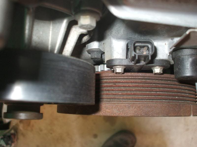
So basicly what I want to know is if I can use a Megajolt Lite Jr with a EEC-IV to run the coil packs, the newer motor is already equiped with the trigger wheel and crank sensor so all I need is the EDIS 6cy module and the Megajolt Lite Jr?
Cheers
Using EDIS with an Australian ford falcon
Moderators: JeffC, rdoherty, stieg, brentp
-
NITROPIXIE
- Posts: 704
- Joined: Sun Sep 07, 2008 1:54 pm
- Location: Fareham, GB
I think it would be possible but would it not be easier to get the ecu from the newer engine and fit it in????
I had a search for the eec iv ecu and only found http://www.auto-diagnostics.info/ford_eec_iv which uses an EDIS unit already for engine speed, pin 56 PIP. Do you know the pin out of your current ecu and how it is triggered for engine speed.
I had a search for the eec iv ecu and only found http://www.auto-diagnostics.info/ford_eec_iv which uses an EDIS unit already for engine speed, pin 56 PIP. Do you know the pin out of your current ecu and how it is triggered for engine speed.
1310 A-series Mini, lightened and built myself. V4 board and loving it
Rasputin22 - The Mini Forum
Rasputin22 - MK1 Golf Forum
Megajolt repair for the UK available
Rasputin22 - The Mini Forum
Rasputin22 - MK1 Golf Forum
Megajolt repair for the UK available
Thanks for the reply!
IIRC the EEC-IV used in my falcon doesn't have the EDIS built in, and fitting the later ECU would require a complete wiring change in the car and requires a $800 unit to flash it for the cam
Heres a pinout for the ECU
EEC-V Wiring Information
1 Keep Alive Power Battery +12V
2 Not used
3 Vehicle Speed Sensor 10V Square wave when driving
4 Smartlock Immobilisation Signal 0V-12V Bus Signal
5 Ignition Power 12V with Ignition On
6 Not Used
7 Engine Coolant Temp 20*C-3.1V, 40*C-2.2V, 100*C-0.5V
8 Fuel Select (Tickford LPG Models Only) Petrol >9Volts, LPG 0Volts
9 Not Used
10 Airconditioning Clutch On 12V Aircon On, 0V Aircon Off
11 Trans Lock Up solenoid (S7) 12V Lockup
12 Economy Indicator Lamp 0V Economy Lamp On
13 LPG Cut Off Solenoid 0V LPG On, 12V LPG Off
14 Transmission Solenoid (S6) 12V Ignition On
15 Broadband Manifold <3800RPM 0V, >3800RPM 12V
16 Ground 0V
17 Self Test Output (STO) PWM signal 0V-12V
18 Not Used
19 Not Used
20 Case Ground 0V
21 Idle Speed Control +8V to +11V Engine Running
22 Fuel Pump Control +12V Ignition On, 0V Engine Running
23 Knock Sensor +3V Engine Running
24 Not Used
25 Intake Air Temperature Sensor 0*C 3.9V, 20*C 3,1V, 40*C 2.2V
26 Not used
27 Auto Trans Power/Econ Switch Normal 12V, Econ 0V
28 Power Steering Pressure Switch 0V No Load, 12V Steering Load
29 HEGO (Oxygen Sensor) Input 0.1V - 0.8V with Engine Running
30 Transmission Position [p]3.8V-4.2V, [R]3.3V-3.7V, [N]2.8V-3.2V, [D]2.3V-2.7V, [3]1.8V-2.2V, [2]1.3V-1.7V, [1]0.8V-1.2V
Manual Transmission, Neutral 0V-0.1V, In gear 5Volts
31 Canister Purge 8V-10V with Engine Running
32 LPG Gas Shut Off LPG Off 12Volts, LPG On 0Volts
33 Electric Fan 2 Output Relay 2 & 3 Off 12V, Relay 2 & 3 On 0V
34 Data Output Link PWM Data
35 Automatic Transmission Solenoid (S3) 0V-12V
36 SPOUT (Spark Output) Ignition 7V average with Engine Running
37 Ignition Power 12V with Ignition On
38 Auto Trans Variable Pressure Solenoid (S5) 10V - 14V with Engine Running
39 Speed Sensitive Power Steering 0V-12V PWM signal
40 Ground 0Volts
41 Air Conditioning Compressor 12Volts Engaged, 0V Off
42 Transmission Oil Temp 20*C-3.5V, Normal Op Temp 1.0-3.6V
43 A/C Evaporator Air Temp 20*C 1.5V-2.0V
44 Blower Fan Speed High Speed 12V, Off 0V
45 MAP Manifold Absolute Pressure sensor Engine Running 100Hz - 105Hz
46 Signal Ground 0Volts
47 Throttle Position Sensor 0.7V closed, 4.5V WOT (Wide Open)
48 Self Test Input 0Volts for Self Test, 12V Normal operation
49 HEGO Ground 0Volts
50 Not Used
51 Auto Trans Gear Select Solenoid (S1) 0Volts off, 12V On
52 Auto Trans Gear Select Solenoid (S1) 0Volts off, 12V On
53 Electric Fan Output 1 12V Relay 1 Off-0V Relay 1 On
54 A/C Relay 0Volts A/C On, 12Volts A/C Off
55 Automatic Transmission Solenoid (S4) 0Volts Off, 12V On
56 PIP Profile Ignition Pick Up 0V - 12V on Ignition PIP
57 Ignition Power 0Volts Off, 12V Ignition On
58 Fuel Injection Ignition Bank 1,3,5 PWM On Fuel Injection
59 Fuel Injection Ignition Bank 1,3,5 0Volts Off, 12V On
60 Ground 0Volts
IIRC the EEC-IV used in my falcon doesn't have the EDIS built in, and fitting the later ECU would require a complete wiring change in the car
Heres a pinout for the ECU
EEC-V Wiring Information
1 Keep Alive Power Battery +12V
2 Not used
3 Vehicle Speed Sensor 10V Square wave when driving
4 Smartlock Immobilisation Signal 0V-12V Bus Signal
5 Ignition Power 12V with Ignition On
6 Not Used
7 Engine Coolant Temp 20*C-3.1V, 40*C-2.2V, 100*C-0.5V
8 Fuel Select (Tickford LPG Models Only) Petrol >9Volts, LPG 0Volts
9 Not Used
10 Airconditioning Clutch On 12V Aircon On, 0V Aircon Off
11 Trans Lock Up solenoid (S7) 12V Lockup
12 Economy Indicator Lamp 0V Economy Lamp On
13 LPG Cut Off Solenoid 0V LPG On, 12V LPG Off
14 Transmission Solenoid (S6) 12V Ignition On
15 Broadband Manifold <3800RPM 0V, >3800RPM 12V
16 Ground 0V
17 Self Test Output (STO) PWM signal 0V-12V
18 Not Used
19 Not Used
20 Case Ground 0V
21 Idle Speed Control +8V to +11V Engine Running
22 Fuel Pump Control +12V Ignition On, 0V Engine Running
23 Knock Sensor +3V Engine Running
24 Not Used
25 Intake Air Temperature Sensor 0*C 3.9V, 20*C 3,1V, 40*C 2.2V
26 Not used
27 Auto Trans Power/Econ Switch Normal 12V, Econ 0V
28 Power Steering Pressure Switch 0V No Load, 12V Steering Load
29 HEGO (Oxygen Sensor) Input 0.1V - 0.8V with Engine Running
30 Transmission Position [p]3.8V-4.2V, [R]3.3V-3.7V, [N]2.8V-3.2V, [D]2.3V-2.7V, [3]1.8V-2.2V, [2]1.3V-1.7V, [1]0.8V-1.2V
Manual Transmission, Neutral 0V-0.1V, In gear 5Volts
31 Canister Purge 8V-10V with Engine Running
32 LPG Gas Shut Off LPG Off 12Volts, LPG On 0Volts
33 Electric Fan 2 Output Relay 2 & 3 Off 12V, Relay 2 & 3 On 0V
34 Data Output Link PWM Data
35 Automatic Transmission Solenoid (S3) 0V-12V
36 SPOUT (Spark Output) Ignition 7V average with Engine Running
37 Ignition Power 12V with Ignition On
38 Auto Trans Variable Pressure Solenoid (S5) 10V - 14V with Engine Running
39 Speed Sensitive Power Steering 0V-12V PWM signal
40 Ground 0Volts
41 Air Conditioning Compressor 12Volts Engaged, 0V Off
42 Transmission Oil Temp 20*C-3.5V, Normal Op Temp 1.0-3.6V
43 A/C Evaporator Air Temp 20*C 1.5V-2.0V
44 Blower Fan Speed High Speed 12V, Off 0V
45 MAP Manifold Absolute Pressure sensor Engine Running 100Hz - 105Hz
46 Signal Ground 0Volts
47 Throttle Position Sensor 0.7V closed, 4.5V WOT (Wide Open)
48 Self Test Input 0Volts for Self Test, 12V Normal operation
49 HEGO Ground 0Volts
50 Not Used
51 Auto Trans Gear Select Solenoid (S1) 0Volts off, 12V On
52 Auto Trans Gear Select Solenoid (S1) 0Volts off, 12V On
53 Electric Fan Output 1 12V Relay 1 Off-0V Relay 1 On
54 A/C Relay 0Volts A/C On, 12Volts A/C Off
55 Automatic Transmission Solenoid (S4) 0Volts Off, 12V On
56 PIP Profile Ignition Pick Up 0V - 12V on Ignition PIP
57 Ignition Power 0Volts Off, 12V Ignition On
58 Fuel Injection Ignition Bank 1,3,5 PWM On Fuel Injection
59 Fuel Injection Ignition Bank 1,3,5 0Volts Off, 12V On
60 Ground 0Volts
-
NITROPIXIE
- Posts: 704
- Joined: Sun Sep 07, 2008 1:54 pm
- Location: Fareham, GB
What we need to do is duplicate the signal which came from the distributor and produce it in the new setup, that way we can trick the ecu into thinking it is still attached. Then you should be able omit the ignition circuit from the ecu and just use the megajolt to run the ignition side of things.
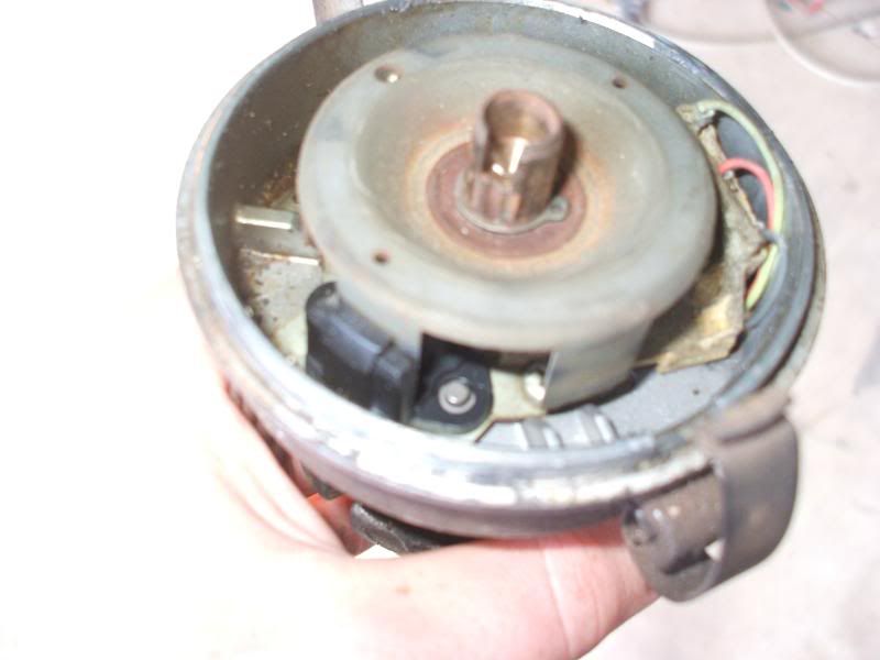
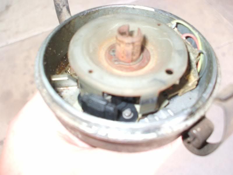
Any chance you can put up a picture of the distributor you have. I'm mainly interested on whats inside the distributor like the points/hall effect pickup if you get what i mean.
Any chance you can put up a picture of the distributor you have. I'm mainly interested on whats inside the distributor like the points/hall effect pickup if you get what i mean.
1310 A-series Mini, lightened and built myself. V4 board and loving it
Rasputin22 - The Mini Forum
Rasputin22 - MK1 Golf Forum
Megajolt repair for the UK available
Rasputin22 - The Mini Forum
Rasputin22 - MK1 Golf Forum
Megajolt repair for the UK available
-
NITROPIXIE
- Posts: 704
- Joined: Sun Sep 07, 2008 1:54 pm
- Location: Fareham, GB
I think this can be very easy. The tfi module produces a PIP (Profile Ignition Pickup) signal, as does the EDIS unit. Now i am pretty sure you could tap this to both the ecu and megajolt from the EDIS. Then just omit the ignition side of things from your ecu and use that for fuel only. Megajolt will then control the ignition.
Does anyone else agree with what i have said?? Or would the PIP signal be diffeent?
The shorter 'blade' is to tell the ecu exactly what position it is for sequential injection systems
Does anyone else agree with what i have said?? Or would the PIP signal be diffeent?
The shorter 'blade' is to tell the ecu exactly what position it is for sequential injection systems
1310 A-series Mini, lightened and built myself. V4 board and loving it
Rasputin22 - The Mini Forum
Rasputin22 - MK1 Golf Forum
Megajolt repair for the UK available
Rasputin22 - The Mini Forum
Rasputin22 - MK1 Golf Forum
Megajolt repair for the UK available
EDboy
Possibly this forum would better answer your original question.
http://www.fordforums.com.au/showthread.php?t=74982

________
Motorcycle Tires
Possibly this forum would better answer your original question.
http://www.fordforums.com.au/showthread.php?t=74982
________
Motorcycle Tires


