
My RPM signal is quite erratic. It frequently jumps high. Is perhaps the configuration incorrect?
I'm getting the RPM signal from the tach in the instrument cluster of my 1987 VW GTI 16V. It's an old fashioned distributor/coil type signal. I'm sampling at 100Hz because I want samples every 10ms. Logging precision is 0. Pulse Mode is RPM. Clock Divider is CLOCK/2. 4 pulses per revolution. This is what I get for around a 900rpm idle.
Are there some better settings to get a more even signal?
Erratic RPM, incorrect configuration?
Moderators: JeffC, rdoherty, stieg, brentp
Erratic RPM, incorrect configuration?
- Attachments
-
- Erratic_RPM.jpg (72.15 KiB) Viewed 24405 times
So from your description it looks like you are tapping into the high voltage kickback pulse from the ignition coil primary. These pulses have a 500v peak and the RaceCapture/Pro inputs are designed for a 40V maximum standard.
You probably need to disconnect that RPM signal ASAP to avoid damage to the system.
In addition to the high voltage, the tach signal is also very which is why you are seeing the erratic RPM signal.
Suggested is an opto-isolated interface that buffers the high voltage tach signal from the input to the RaceCapture/Pro tach input.
We're testing this design right now:
https://github.com/autosportlabs/CoilX
If this is something you'd like to test as well, let us know and we can send out a board when they're ready!
there are other interface circuits out there as well.
Bottom line: know the kind of connection you're making to RaceCapture/pro before hooking up a line. The input/outputs are protected up to a point, but nothing is bullet proof!
More info:
What you see on the top trace is the typical trace seen from the ignition coil primary when the coil fires:

The bottom trace is from testing a version of the optoisolator interface board we're currently working on. You can see a glitch triggered by the secondary ringing of the pulse. This has been largely resolved by switching the zener diode in the design from 24v to 75v to clip off the peaks of that secondary pulse.
What you see on the top trace is the typical trace seen from the ignition coil primary when the coil fires:
The bottom trace is from testing a version of the optoisolator interface board we're currently working on. You can see a glitch triggered by the secondary ringing of the pulse. This has been largely resolved by switching the zener diode in the design from 24v to 75v to clip off the peaks of that secondary pulse.
I'm having a similar issue (although not nearly as bad), but I don't think the cause is the same. I am getting my RPM signal off my Hydra Nemesis EMS from the 5v coil driver (since it happens to be a convenient 5v RPM source). I had to enable wasted spark to get it scaled correctly since the software won't allow you to specify less than 1 pulse per revolution (4 cylinder, 4 individual direct fire coils), but it seems to be mostly working.
However, I am getting intermittent spikes, both high and low, as shown below:
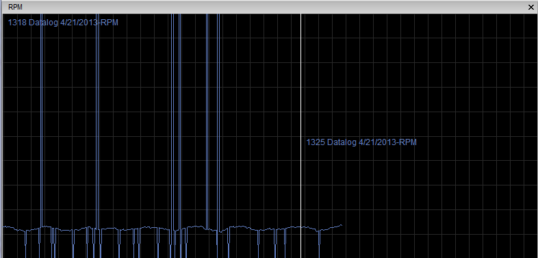
Is it possibly an issue with the length of the pulse, since it is the coil charge / fire signal that I am tapping into?
My other option is the 12v tach output from the ECU. I know the max that the RCP can sense is 5v, but the inputs are protected up to 45v Would it work properly with a 12v signal, since it will still see a pulse, even if the max amplitude of that pulse is higher than it can read, it should appear like a 5v pulse to the RaceCapture? Or am I thinking about that wrong?
I as well tapped into the RPM signal feeding the OEM tach in the gauge cluster of my E30, and I'm not getting a quality RPM reading. I've changed the 'pulses per minute' and it seems to do nothing. I've run back to back test with it at 1 and 10 at just to see if the RPM value drops by a factor of 10, and it doesn't.
Brent, you're saying that usually the ECU gets it's tach signal from the - side of the coil, giving high peak voltages. The line I tapped into is coming out of the ECU which may or may not still have the high voltage spikes. Would it be better to tap into the crank position sensor at the front damper or would that signal not be clean enough for the logger read a frequency without being processes before hand?
Brent, you're saying that usually the ECU gets it's tach signal from the - side of the coil, giving high peak voltages. The line I tapped into is coming out of the ECU which may or may not still have the high voltage spikes. Would it be better to tap into the crank position sensor at the front damper or would that signal not be clean enough for the logger read a frequency without being processes before hand?
Alex, would you be able to 'scope the signal coming out of the coil pack trigger, measuring it from the input to RaceCapture/Pro? If you could post a picture of the trace that would be ideal. And yes, you can connect a 12v square wave to the tach input; the internal protection diodes will clamp the voltage.
@barkerdm - I'm not familiar with the tach signal on your E30 - you might want to check any technical resources to see what that signal looks like. Also good to measure it directly to see what the waveform looks like.
Overall, RaceCapture/Pro needs a clean, square signal otherwise the noise can be registered as extra pulses, affecting the RPM reading, which shows up as high rpm spikes. There's a certain amount of filtering we can do in the firmware that I'm going to investigate.
For interfacing directly to the coil pack primary (old style tach connection) I just tested an updated opto-isolated coil interface with great success. You can find the information here: https://github.com/autosportlabs/CoilX
I'm ordering some test boards and will have them available in about 1.5 weeks. If anyone wants to receive one of these to test, email me at brent (at) autosportlabs.com!
OK, so I switched to the 12v square wave tach output from the ECU and it solve that problem, nice smooth RPM trace now. Unfortunately, I know have a different issue... I can't get it to read anything other than 2x the actual speed. I initially set it up for 2 pulses per rev, saw that it was reading at 2x, so I changed it to 4 pulses per rev, but the reading is still double what it should be. How is that possible?
Well, that sounds like it might be a bug. when you change the config, read it back after a power cycle with RaceCapture/Pro and make sure it sticks. it should dynamically change. I shall double check it on my end- I remember testing this rather explicitly (grumble grumble)
Glad to see you got a smooth signal from the ECU. Can you post a screen grab or a sample logfile?
Glad to see you got a smooth signal from the ECU. Can you post a screen grab or a sample logfile?
Graph looks like this now:
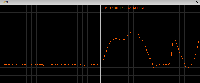
This was logged at 10hz, which may account for a little of the jitteryness of the graph.
I never went back and double checked that the change from 2 pulse/rev to 4 had "stuck", but when I went to make the change from 2 to 4 the original change from 1 to 2 was definitely showing in the config that I read from the hardware.
Scope trace as requested.
Waveform A is what I was trying to log with the RaceCapture Pro when I got the erratic signal above that started this thread. This is the tach signal to the cluster and comes from the coil -1 terminal. It has approximately a 35V peak, so no danger in damaging my unit. The time period exactly agrees with the other rpm signal available on my vehicle. The thing is, I would really prefer to use the signal on Waveform A because it is already at the cluster and easiest to tap into. And since the tach on the instrument panel can comprehend this signal it should also be possible for other devices to do the same.
Waveform B is the rpm signal between the knock box and the KE-Jetronic on my car. This is pin 25 on the KE-Jetronic (yes, I built my own breakout box. ). Clearly the ignition control module, aka knock box, beautifies the signal. It is the nice square wave that Brent said the RaceCapture Pro likes and has a peak of around 12V (notice the different scaline). Same time period as the tach signal.
Oh, and if you feel like doing the math, the engine was idling at around 950rpm when the scope display was put on hold for this screenshot. The camshaft should turn at half speed of the crank. The 30ms pulse period agrees with the tach reading of around 1000rpm.
So Brent, you've got PM regarding your signal converter.
Waveform A is what I was trying to log with the RaceCapture Pro when I got the erratic signal above that started this thread. This is the tach signal to the cluster and comes from the coil -1 terminal. It has approximately a 35V peak, so no danger in damaging my unit. The time period exactly agrees with the other rpm signal available on my vehicle. The thing is, I would really prefer to use the signal on Waveform A because it is already at the cluster and easiest to tap into. And since the tach on the instrument panel can comprehend this signal it should also be possible for other devices to do the same.
Waveform B is the rpm signal between the knock box and the KE-Jetronic on my car. This is pin 25 on the KE-Jetronic (yes, I built my own breakout box.
Oh, and if you feel like doing the math, the engine was idling at around 950rpm when the scope display was put on hold for this screenshot. The camshaft should turn at half speed of the crank. The 30ms pulse period agrees with the tach reading of around 1000rpm.
So Brent, you've got PM regarding your signal converter.
- Attachments
-
- RPMsignalsAt950rpm.JPG (188.57 KiB) Viewed 24296 times