MJLJ Stimulator...with some pics

General Topics for configuring, operating and tuning the Megajolt. Also see the <a href="http://www.autosportlabs.net/MJLJ_V4_Operation_Guide">Operation Guide</a>

Moderators: JeffC, rdoherty, stieg, brentp

Post Reply
MartinM
Posts: 433
Joined: Sat Aug 27, 2005 12:08 pm

MJLJ Stimulator...with some pics

Post by MartinM »

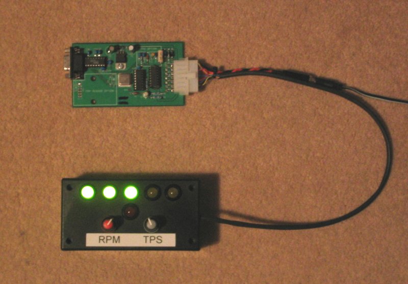
Here's something I knocked up for fun - just connect +12v to the connector near the Molex, the Molex into the MJLJ and the computer to the MJLJ and the rest should be self-explanatory from the picture!

Only components are the LEDs, some series resistors and an Atmel AVR (ATTiny13 - about GBP0.75) with about 75 lines of assembly code....

Image

Image

brentp
Site Admin
Posts: 6282
Joined: Wed Jan 24, 2007 6:36 am

Post by brentp »

Looks neat! I'll post pics of mine, but yours wins in sophistication, I only used a 555 timer to stimulate PIP. :wink:

I'm also building a new test bench for more elaborate testing, I'll post pictures of that as well!
Brent Picasso
CEO and Founder, Autosport Labs
Facebook | Twitter

MartinM
Posts: 433
Joined: Sat Aug 27, 2005 12:08 pm

Post by MartinM »

I used software so that I could get the rpm (500-8500) to be linear with the pot rotation - the ATTiny13 has an onboard ADC, so I thought I might as well use it!

It's not really a test bench, since it doesn't take any notice of PIP - that's the MkII version I suppose

It also, obviously, only does Engine Load as TPS - I still have my trusty syringe and windscreen washer pipe for MAP :)

brentp
Site Admin
Posts: 6282
Joined: Wed Jan 24, 2007 6:36 am

Post by brentp »

No kidding on the non-linearity! the last few 1000 RPMs are a bit touchy!

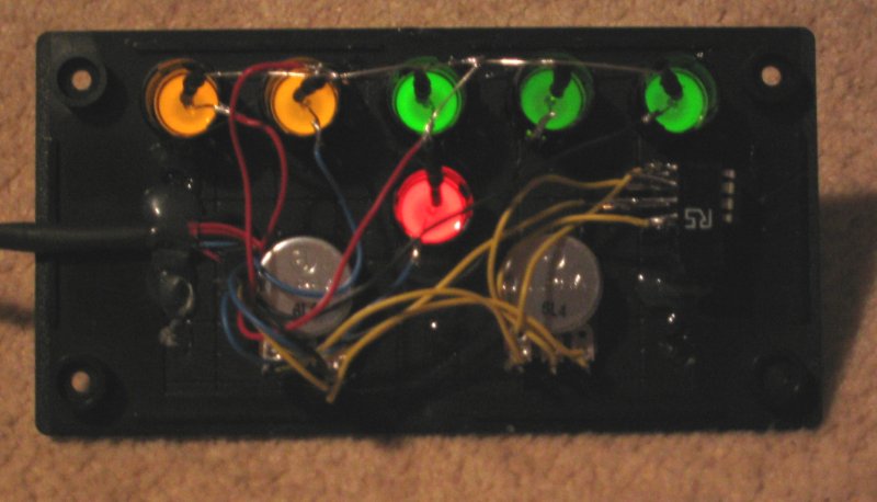
I've attached pictures of my abomination :D it's not pretty but it does the job. The MJLJ unit it's attached to is the grandpappy first MJLJ v2.0.

You know what works great for testing the map sensor? One of those rubber bulbs used for clearing an infant's nose. Cleaned, of course. :D
Attachments
stimulator closeup
stimulator closeup
stimulator_closeup.jpg (73.42 KiB) Viewed 9125 times
stimulator
stimulator
mjlj_stimulator.jpg (66.59 KiB) Viewed 9125 times

Spockie-Tech
Posts: 152
Joined: Wed Jan 02, 2008 12:52 pm
Location: Melbourne, Australia

Post by Spockie-Tech »

Hi Martin

I relaise this is an old thread, but I have just completed two Megajolt/EDIS's, and am interested in the source code to your driver micro if you will share it.

I have AVR programming facilities, and even a ATTiny on the shelf !, so is you code and a diagram available please ?

regards

Brett

MartinM
Posts: 433
Joined: Sat Aug 27, 2005 12:08 pm

Post by MartinM »

Hi Brett

AVR Studio 4 files attached. Enjoy!

Any questions, just ask - post here or PM.

Let me know if they make sense - if so, I'll post the schematic ....

Regards
Martin
Attachments
MJLJStimulator.zip
MJLJ Stimulator V1.0
(16.1 KiB) Downloaded 660 times

Spockie-Tech
Posts: 152
Joined: Wed Jan 02, 2008 12:52 pm
Location: Melbourne, Australia

Post by Spockie-Tech »

Thank you very much Martin !

Got them open in AVR Studio and perusing them now.

AVR Assembly code is new to me ( did some 90s1200 code a few years ago), but I've done plenty of coding on Pics, Z8's, 68x and so on, they're all similair, so its looking straight forward enough.

get an ADC input, use that as an offset into a lookup table to compare against an interrupt driven counter. nicely formatted :)

I've been meaning to get into some AVR coding for a while (I have a Mega32 and 90Can128 on the bench here to do some Can/Lin bus projects for my car as well a Megajolt)) - so this is a good excuse to get moving on it

Now I need to do some datasheet browsing - The Tiny I have is a 15L - I have to see what the difference between that an the 13 is.

If you have a schematic handy that would be useful, but with only 8 pins, I'm sure I can figure it out if its not convenient.

Has anyone thought of adding a temperature input to the MJLJ ?

I was thinking of analog tweaking the Map input with a coolant sensor modifier so as to pull the advance back a bit on hot days without having to mess up the existing code or configurator.
jonboylaw
Posts: 8
Joined: Mon Feb 25, 2008 3:06 pm

Circuit diagram please :)

Post by jonboylaw »

I also would welcome a circuit diagram.


Jon

MartinM
Posts: 433
Joined: Sat Aug 27, 2005 12:08 pm

Post by MartinM »

Sorry chaps - completely forgot :(

Here's a very badly laid out schematic on a scrappy piece of paper inelegantly scanned...
Image

jonboylaw
Posts: 8
Joined: Mon Feb 25, 2008 3:06 pm

Post by jonboylaw »

Cheers Martin

:D :D

Post Reply